
Testing models for any product using two-dimensional (2D) simulation lack the ability to predict dimensional variation in real-world production. These dimensional variations cause non-conformance and defects in manufacturing that require assembled machines to be adjusted or retooled to fix problems, as well as contributing to scrap and rework of parts. This is especially the case when dealing with gear assemblies.
Dimensional Control Systems (DCS) has achieved the ability to model complex gear assemblies within its 3DCS software and is excited to offer this as a new service. Join DCS September 24th for an informative webinar to learn more.
Watch NOW On-Demand

Three-dimensional (3D) simulation helps businesses reduce lead and launch time with improvements in the prototype build. The program is able to create thousands of samples within the variance of each gear to determine the optimal tolerances for noise, vibration, and durability requirements.
This functionality helps minimize problems with prototype builds, saving time and money on costly retooling. The results create gear assemblies with little variation. Additionally, the ability to use coarse and fine testing allows engineering staff to efficiently test multiple models before fine-tuning analysis on the best model.
Furthermore, the ability to determine the variation contributor and test corrective actions via the simulation creates a digital validation of the design, eliminating the need to create multiple physical prototypes for testing or to solve build issues before production.
Gears need to work together, and identifying and fixing the root cause of misalignment before production begins is critical. Even the slightest misalignment can reduce performance, leading to lengthy delays spent identifying and fixing the issue and often involving high-cost corrective actions.
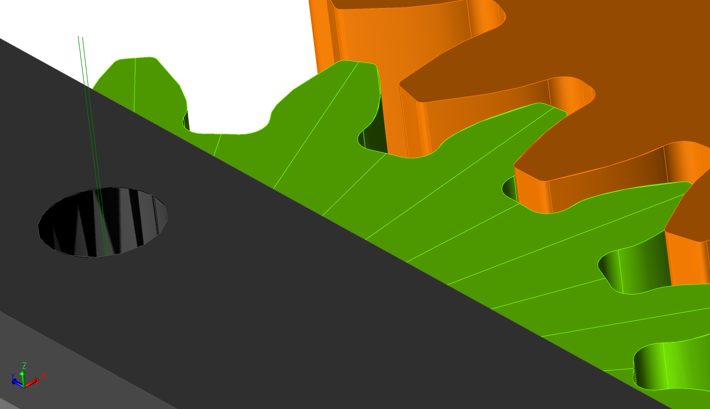
Traditional 2D models are static drawings, and while they can be layered, they fail to truly simulate the gear parts in 3D. Any variation in housing, bearing, or gear meshing across the gear cycle could be responsible for the misalignment.
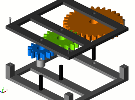
3DCS allows engineers to create simulation models with the individual parts and components and produce gear cycle process variation testing. This model looks at variations within the manufacturing process and their effects on assembly and final product functionality.
3DCS variation analysis can create thousands of models to test part tolerances, simulate the assembly process and perform product measures, creating the opportunity to predict and fix quality issues before production begins.
The 3D model utilizes multiple measures and analytics that compare the variation tolerances of each component and the way the finished gear mechanism works with each of these variations — individually, as they are produced.
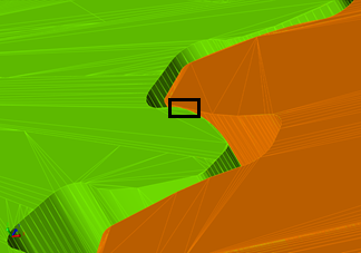
It can analyze tooth contact and complex gear and mechanism dynamics with high accuracy, as well as fix issues with adjustments in bearings, shims, and pinion nut adjustment. This ability provides the flexibility to make small changes that create a gear structure with minimal problems.
3DCS can assess gear backlash and mounting misalignment, perform angular backlash analysis, and create flank test displays, and contact patterns. Here are some of the measurements it supports:
Plus, it supports both fine and coarse gear modeling, depending on the gear and business requirements.
Running a coarse study allows engineers to create models faster and validate the design intent for geometry, tolerances, and measurements. This functionality can be used to eliminate infeasible models, and since the creation is fast, multiple virtual prototypes can be created and compared. The measurements at this level of functioning are only a rough estimate, but the fine study subsequently tweaks the models.
Fine study uses a full tooth contact method for highly accurate results. The additional development time and slower testing speed is required to provide the full suite of measurement and analysis tools. With a 3DCS Fine Gear Study, Engineering will be equipped to avoid misalignment and risk factors that directly impact gear performance and durability.
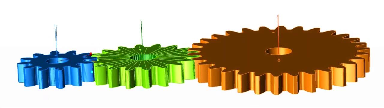
Refining to a fine study does add to the development time and testing runs much slower, but it uses full tooth contact analysis for more accurate results. A full suite of measurement and analysis tools is available to optimize tolerance and measurement accuracy.
Click below to watch the webinar recording on-demand - Gear Modeling from Tom Oetjens, CAE Integrations


North American Innovation Center
28064 Center Oaks Ct A, Wixom, MI 48393
Call us: +1 (248) 504 6200


Comments (1)