
Integrated tolerance analysis makes it easy to take advantage of CAD PMI and GD&T. Many CAD platforms have tools to create and validate GD&T, and can be used to improve the DVA process.
Many CAD systems have built-in tools to help designers and engineers apply GD&T to their models and validate the annotations.
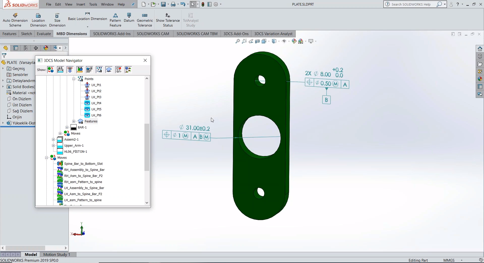
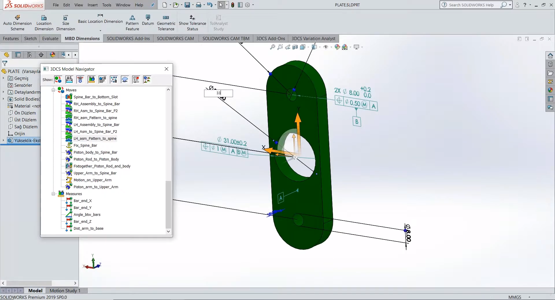
SOLIDWORKS® Model-Based Definition (MBD) lets you define and organize 3D dimensions, tolerances, datums, notes, Bills of Material (BOMs), and other annotations; customize publishing templates for manufacturing, such as Part or Assembly Specifications, Request for Quote (RFQ), and Incoming Inspection Reports. You can also publish to widely accepted formats, such as eDrawings®, STEP 242, and 3D PDF for clear 3D communications.
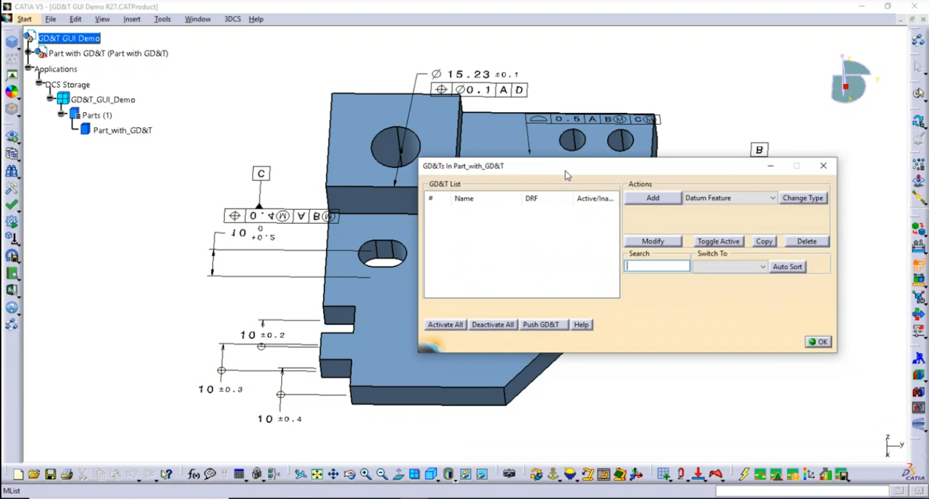
Tolerance Advisor is a helpful tool in CATIA V5 that assists with GD&T and Tolerances. With a few clicks, Tolerance Advisor can help the user add GD&T, link surfaces and add other characteristics to their model.
• Create datums and tolerances
• Keep GD&T linked with selected surfaces
• Create reference frames with datums
https://blog.3dcs.com/Blog/bid/74090/Common-Uses-for-Tolerance-Advisor-Tips-and-Tactics
Takeaways:
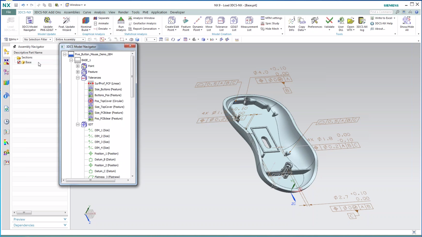
Setting up your PMI ahead of time helps you create your Datums and GD&T in association with your model. Having this information early gives the dimensional team enough time to optimize and validate the GD&T before pushing it back to the CAD for use downstream.
Learn how in DCS' Webinar on NX PMI:
https://mkt.3dcs.com/digital-gdandt-create-in-cad-catia-nx-creo
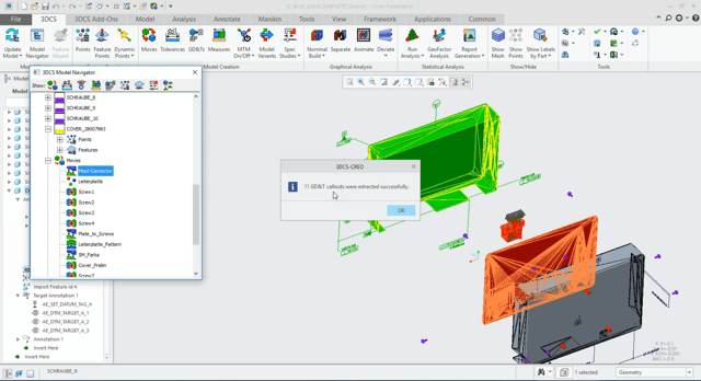
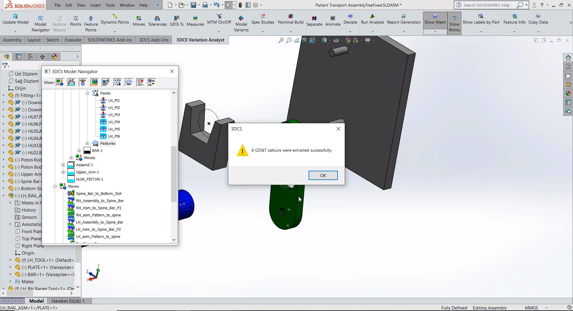
Reading the GD&T into 3DCS is simple. For the integrated versions, it is a single button push that pulls in the semantic GD&T callouts. For the standalone version, 3DCS Multi-CAD, it requires the import of the native CAD files to bring the PMI or FTA with them, as opposed to using STEP or IGES.
Once read in, 3DCS can be used to simulate the tolerances and determine the effect of the variation on the assembly. This provides a number of valuable outcomes like:
CAD model and part updates are common during most product life-cycles and design phases, but can be difficult to incorporate into existing studies. 3DCS streamlines this process to make it easy to update existing and current analyses.
 Dimensional engineers are often setting up their models and studies while the design team continues to revise the CAD model that the analyses are based upon. As the designers continue to revise the model with engineering changes, design changes, and process changes, these updated CAD parts are passed to the engineers who need to update their studies.
In many cases, this can cause issues, as 1D stacks and many Excel based studies need to be started from the beginning with new parts, changes in hole sizes or location, or the addition of new features. 3DCS, however, has some quick tools to bypass these issues, making the use of new and updated parts easy.
Click to learn more about updating your model with part changes
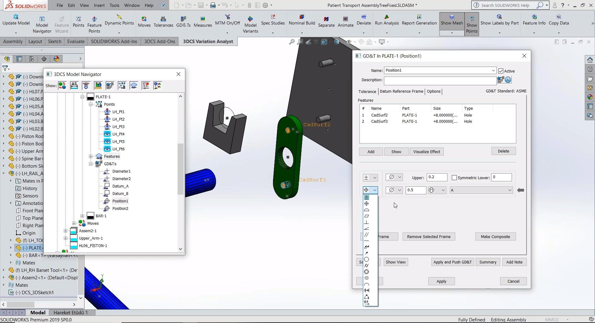
3DCS allows you to build your model in two ways (or combination of both):
1. Read in semantic GD&T from CAD along with Joints and Constraints
2. Create Tolerances (and/or GD&T), Moves, and Measurements directly in 3DCS
Combining these two methods produces a Digital Twin to provide insight into the design and help engineers and designers adjust the design, not just tolerances, in order to control variation and reduce risk.


North American Innovation Center
28064 Center Oaks Ct A, Wixom, MI 48393
Call us: +1 (248) 504 6200


No Comments Yet
Let us know what you think