 Dimensional engineers are often setting up their models and studies while the design team continues to revise the CAD model that the analyses are based upon. As the designers continue to revise the model with engineering changes, design changes, and process changes, these updated CAD parts are passed to the engineers who need to update their studies.
In many cases, this can cause issues, as 1D stacks and many Excel based studies need to be started from the beginning with new parts, changes in hole sizes or location, or the addition of new features. 3DCS, however, has some quick tools to bypass these issues, making the use of new and updated parts easy.
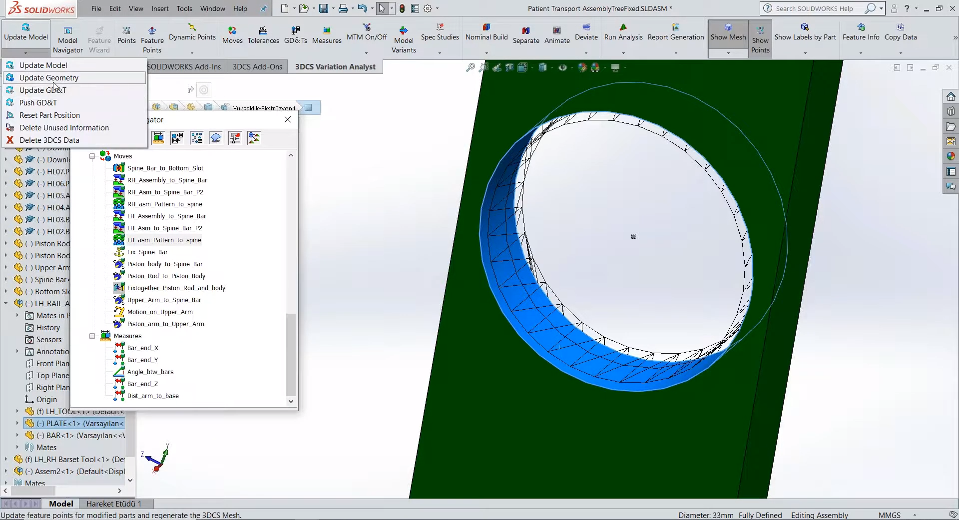
When new parts are available, the CAD software will incorporate them upon opening. 3DCS uses a mesh overlay that it deforms based on tolerances and GD&T inputs. The mesh is updated when Update Geometry is selected from the drop down menu. This updates the mesh to mirror the new CAD geometry.

The software meshes any components that have connected features or tolerances (associated GD&T) automatically. This speeds up analysis and allows the user to control the density of the mesh, choosing between speed of analysis and complexity of the result.
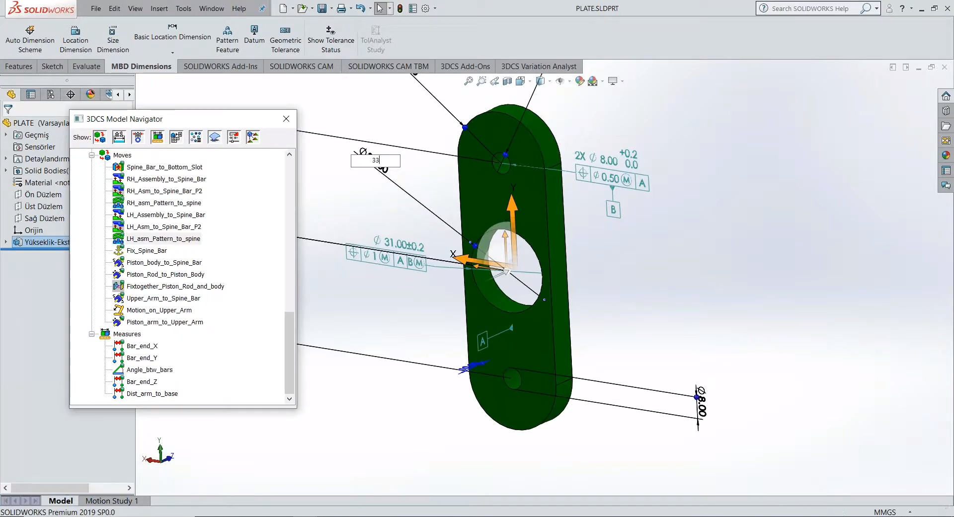
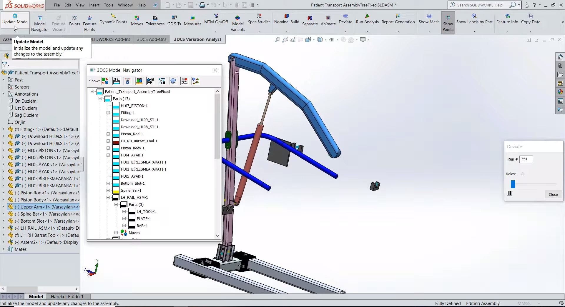
In the example below, one of the side bar brackets on a medical lift assist has its hole diameter set to a larger size. When the part is changed and loaded into the CAD system, the 3DCS model is updated with the new part specifications. By clicking on the Update Geometry button, the hole automatically meshes and deviates based on the GD&T.
It is important to note that the mesh does not automatically update to the new changes until the user updates it. This allows the software to produce the same result until chosen to change the mesh to the new geometric location. With this feature, the user can set the original as a variant or save it as an alternate model, creating a comparison between the before and after design, or storing a historical backup before updating the mesh with the new geometry.
If the designer deleted a hole and created a new hole, the model would lose the feature link and there is a quick process to link the new hole to the feature. This means that any change to the model, whether changing the size or position of holes, the shape of parts, the process of the parts, can be quickly incorporated into the dimensional variation study without starting over or forcing the user to re-do previous steps.


North American Innovation Center
28064 Center Oaks Ct A, Wixom, MI 48393
Call us: +1 (248) 504 6200


No Comments Yet
Let us know what you think