
3DCS is now fully integrated with SOLIDWORKS. Inside the SOLIDWORKS platform, 3DCS is activated as two add-on workbenches:
See how an assembly in SOLIDWORKS can be digitally assembled
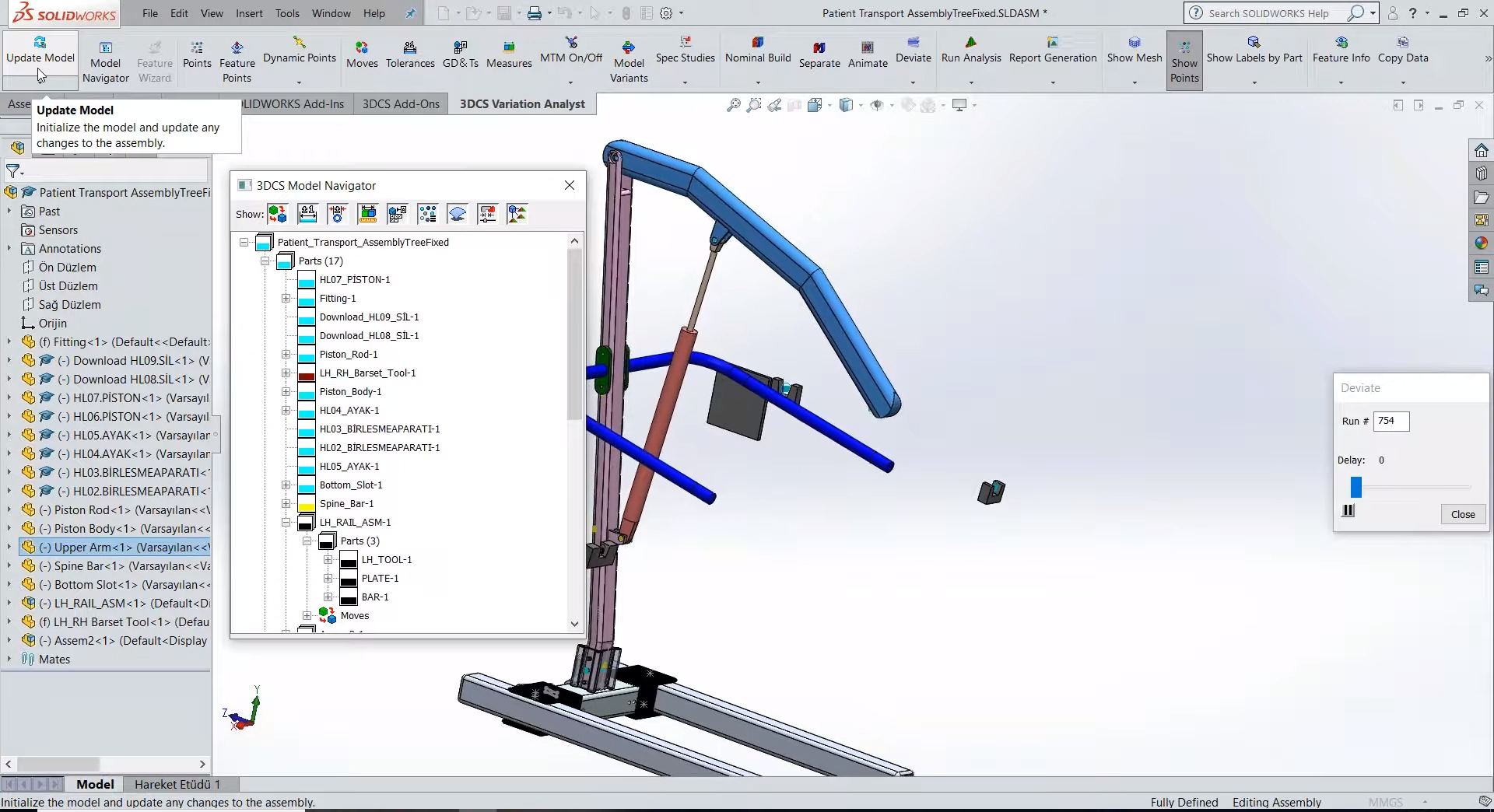
Users will take advantage of the 3DCS Model Navigator Tree which contains all of your 3DCS data. When opening a new model, you'll need to use the Update Model feature to update the 3DCS Model Navigator with the SOLIDWORKS CAD. This is important to note, because this same feature can be used to update your 3DCS model DVA with any CAD changes such as design and engineering changes, that are added later.
As a note: Users do not need to start over or make any adjustments to the model in order to update the CAD geometry, although some moves may need to be adjusted if the geometry changes in a significant way.
The model can be deviated, shifting the parts based on the tolerances and moves added to the model. This is a great way to validate your model and check for major issues quickly.
In this example model dimensional variation analysis, using a medical lift assist, the angle between the two dark blue rods, the handlebars used to help patients pull themselves up, needs to be even. These are going to be checked with an angle measure between the two rods.
Because of the plate connecting the rods to the spine of the device, there is a lot of deviation inherent in the assembly process from pinning the two plates in place and the float from attaching the arm rod to the plate. Using a pattern move to connect the plates to the spine rod, we can use a quick analysis to show significant issues in the final assembly.
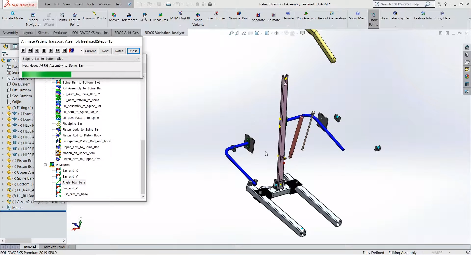
In this model, in order to better control the angular variation, a fixture tool is added as a precursor process to set the arm rods with the plate and control the final positions of the two arms. By using Multi-Stage Assembly, we are able to track the variation through each stage of the assembly, determining where the variation issues are stemming from as well as simulating each stage in the overall assembly process. This becomes even more important in larger assembly models, where the parts may go through a dozen assembly steps and welded, fixed, or pinned into multiple sub-assemblies before being combined into the final assembly.
Many assemblies use joints and constraints in addition to bolts, pins, slots, and holes. By using the Mechanical Modeler Add-on module, we are able to combine the joints and constraints of the upper arm with the hole-pin pattern moves of the side rod arms to the spine column. This allows for mechanical motion on the upper arm and validation of the devices function with variation incorporated.


North American Innovation Center
28064 Center Oaks Ct A, Wixom, MI 48393
Call us: +1 (248) 504 6200


No Comments Yet
Let us know what you think