In design, different methods of assembly, tolerance schemes, and tooling / fixturing need to be considered. Oftentimes, on the same model, there are a plethora of assembly processes that can be used to achieve the same end result. Some of these processes cost more, some are more complicated and some require special skills. The question Designers and Engineers ask when designing their product is; which process and what tolerance should I use?
There are a number of answers to this question. In the CAD model, different processes and tolerances can be validated through simulation to find optimal configurations. The optimal configuration, the right answer, is different for each product as the highest level of quality does not mean the same thing as the tightest tolerances, or fewest steps in assembly or cheapest manufacturing process, but a combination of these in order to get the final result of the lowest risk of assembly failure with the lowest cost factors while still providing a high quality experience for the consumer.

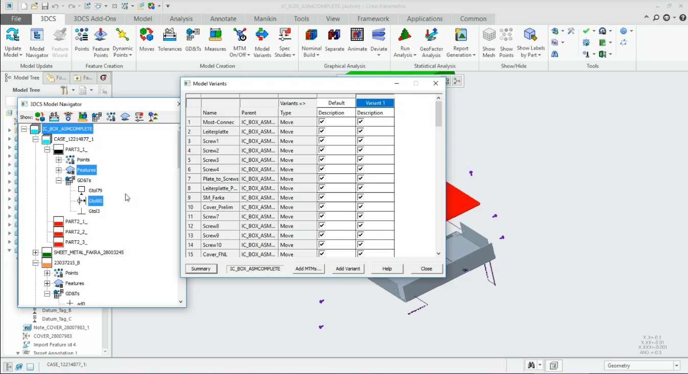
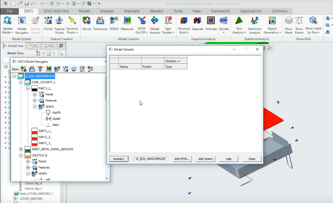
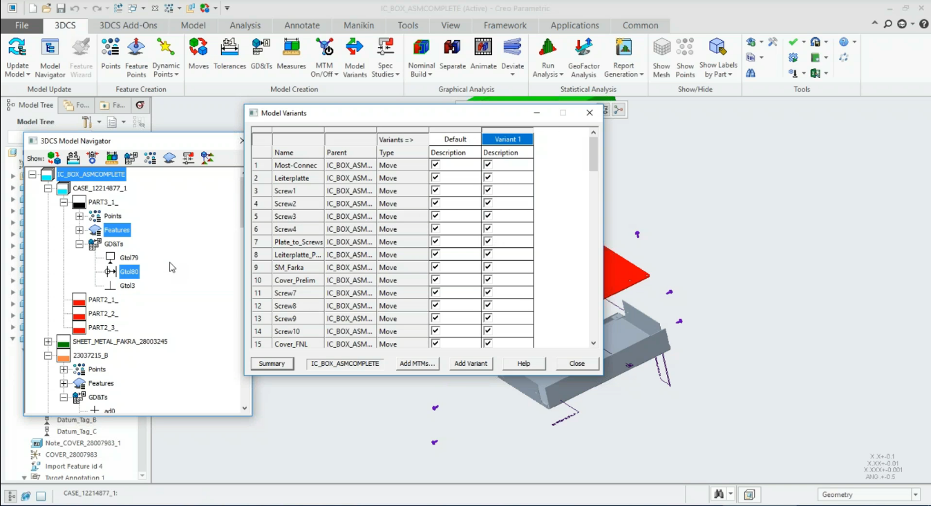
3DCS Model Variants Dialog
In order to find optimal settings, different design configurations need to be tested and compared. Model Variants can be helpful for other uses as well, such as separating advanced portions of the model, or creating historical versions. These configurations may include scenarios such as:
After running initial simulations and identifying the primary contributors, those contributors are then tightened (made smaller) to see the effect on the final builds. By using Model Variants, you can keep your 'original model' and begin creating 'test variants' with new values without losing the original.
Fixtures are often used during assembly processes. The fixtures themselves can add, or reduce variation in the process. Creating a variant with a fixture lets you quickly compare between the model variant with and the model variant without as well as look at different fixture strategies and their affect on assembly variation.
To reduce manufacturing costs, companies are always trying to loosen tolerances (increase range). After simulation, non-critical areas on the model can be identified, and a model variant can be created with loosened tolerances to see the impact on product quality. If the impact is small, those tolerances can remain larger to make manufacturing the components easier for plants and suppliers.
Many assembly processes are done in a sequence that affects the parts. Welding causes material distortion, and the order of operations for a series of bolts can affect the overall part variation. The same applies to riveting, especially when considering material like aluminium that stretches. Creating different variants for different order of operations lets users quickly look at how these sequences affect the parts and overall assembly.
Model Variants can be used to compare supplier quality. After collecting data from suppliers (preferably using a Supplier Quality Portal), 3DCS users can pull that data into 3DCS, comparing the supplier production quality versus simulation results. This makes it easy to parse models based on data sources, creating differing variants based on production lines, locations or suppliers.
Many modelers begin using 3DCS to simulate production risks before the design team has released official CAD or embedded GD&T and PMI. They do so with coordinate points, historical data and industrial knowledge (scroll to the Hella story). Many engineers may also receive incomplete CAD data to begin their modeling, and receive completed CAD at a later time. 3DCS easily supports these kinds of circumstances with point based modeling, but after creating an early model for simulation, a model variant may make sense once the embedded GD&T (PMI) is released, compared against the 3DCS tolerances and GD&T and optimization that has already been completed in the model.
DCS modelers prefer to keep Compliant moves separate so that the model can be run as either a Rigid Body model or a Finite Element Analysis (FEA) Compliant model. Model Variants make this much easier, with one variant for the Rigid Body version and the second for the Compliant version.

Users can select specific Moves, Tolerances and Measurements to include in the variant. This is helpful when, for example, using a few Compliant moves or adding a Fixture move to the model.
This option, found by right clicking on the Model Variant dialog box, brings all Moves, Tolerances and Measures into the current Model Variant. This is a great place to start, adding all current model MTM's to the variant.
These Stories on CATIA
No Comments Yet
Let us know what you think