
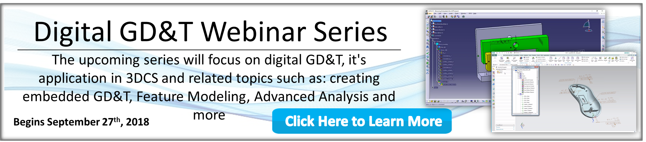
When creating GD&T in CAD, it is important to set your Datums first. They determine the reference points for your other callouts. Different CAD systems have tools to help you create Datums, but understanding where they should be created often requires some experience with GD&T. CAD systems have progressed, but their GD&T creation tools for creating PMI and FTA still require the user to make determinations that are not corrected or checked by the system. The following clips from the DCS Digital GD&T Webinar Series help show how to create Datums in the CAD system, and offer tips and advice on creating Datums that can help you dodge common mistakes.
According to ANSI Y14.5M, an Engineering Datum is a feature on an object used to create a reference system for measurement. The Datums, usually labelled A, B and C, determine the reference point, surface, or axis on an object against which measurements are made. Essentially, they create the 0,0,0 starting point from which all measurements should be determined.
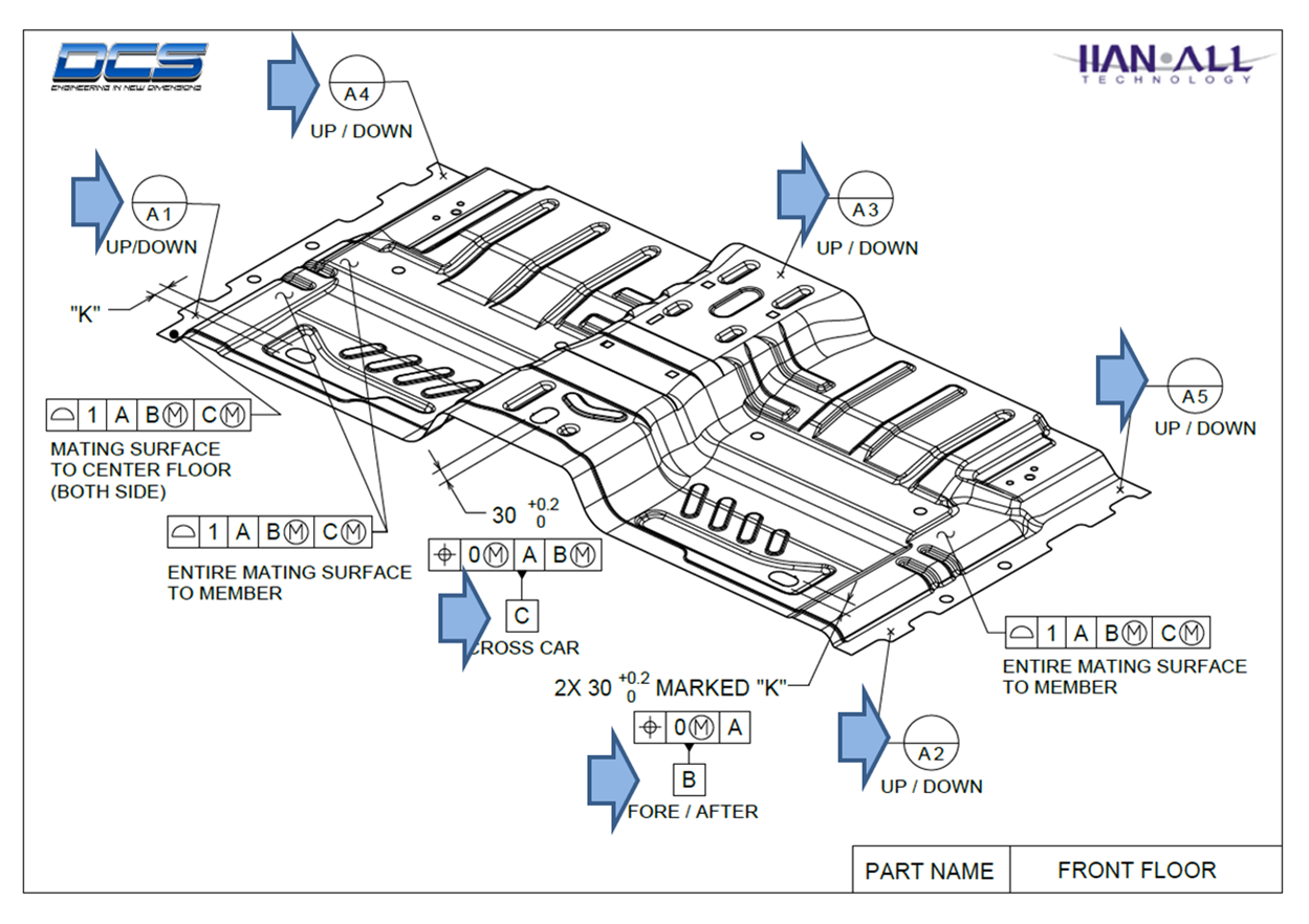
In geometric dimensioning and tolerancing, datum reference frames are typically 3D. Datum reference frames are used as part of the feature control frame to show where the measurement is taken from. A typical datum reference frame is made up of three planes. For example, the three planes could be one "face side" and two "datum edges". These three planes are marked A, B and C, where A is the face side, B is the first datum edge, and C is the second datum edge. In this case, the datum reference frame is A/B/C. A/B/C is shown at the end of feature control frame to show from where the measurement is taken. (See the ASME standard Y14.5M-2009 for more examples and material modifiers.)
The engineer selects A/B/C based on the dimensional function of the part. The datums should be functional per the ASME standard. Typically, a part is required to fit with other parts. So, the functional datums are chosen based on how the part attaches. Note: Typically, the functional datums are not used to manufacture the part. The manufacturing datums are typically different from the functional datums to save cost, improve process speed, and repeatability. A tolerance analysis may be needed in many cases to convert between the functional datums and the manufacturing datums. Computer software can be purchased for dimensional analysis. A trained engineer is required to run the software.
There are typically 6 degrees of freedom that need to be considered by the engineer before choosing which feature is A, B, or C. For this example, A is the primary datum, B is the secondary, and C is the tertiary datum. The primary datum controls the most degrees of freedom. The tertiary datum controls the least degrees of freedom. For this example, of a block of wood, Datum A controls 3 degrees of freedom, B controls 2 degrees of freedom, and C controls 1 degree of freedom. 3+2+1 = 6, all 6 degrees of freedom are considered.
The 6 degrees of freedom in this example are 3 translation and 3 rotation about the 3D coordinate system. Datum A controls 3: translation along the Z axis, rotation about the x axis, and rotation about the y axis. Datum B controls 2: translation along the y axis and rotation about the z axis. Finally, Datum C controls 1 degree of freedom, namely the translation along the x axis. - Datum reference Wikipedia
With two methods of creating Datums, a traditional method and GD&T Advisor, CATIA makes it easy to create Datums on your model. The Semantic Tolerancing Advisor helps suggest callouts for your GD&T to help reduce user error and speed up the process. It can also catch some errors, such as a profile callout placed on a hole.
These videos show how to create the Datums in CATIA, as well as some creation and display tips that make it easier to see and show your FTA (embedded GD&T).
Click Here to See the Full Webinar On-Demand
Using the Annotate tab where the options for Annotations and Annotation Features, either of which can be used to create PMI. Activating Annotations gives access to the toolkit, and the reference frame which is set against the referring feature. This opens the Geometric Tolerance tab which then allows the user to edit the feature control frame that was added to the model. After selecting okay, the type of feature needs to be edited and the Datums selected.
In creating the Datum, Datum Target Annotation Feature is used which lets the user create both the Datum feature and the GD&T for that feature both, saving you some time in modeling. The Datum Feature dialog let's you completed the Datum.
This video shows how to create the Datum Features and offers some display and creation tips to make the process easier.
Click Here to See the Full Webinar On-Demand
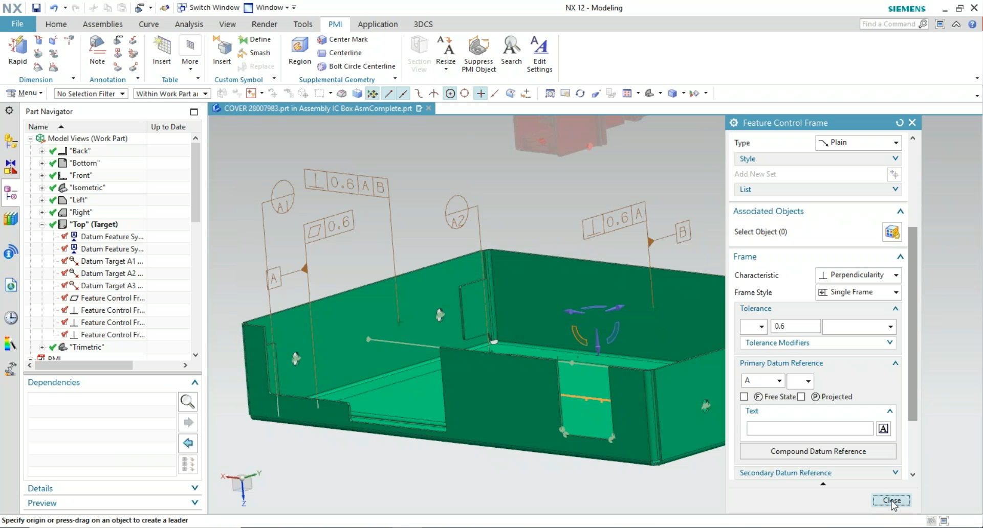
Beginning with a 2D Drawing, Jason Brehmer, DCS Variation Analyst, shows how to create the PMI on a model beginning with the Datums. Using Application Tab, and using the Datum Target option, you select your points to use at feature connections. NX requires that an NX point is on any surface that you want to add PMI to. With Position or a Hole profile, you need to select a feature instead.
This video gives some tips on creating PMI in NX, and how to set up your Datums.
Click Here to See the Full Webinar On-Demand


North American Innovation Center
28064 Center Oaks Ct A, Wixom, MI 48393
Call us: +1 (248) 504 6200


No Comments Yet
Let us know what you think