DCS has already covered creating Datums in the CAD platforms - CATIA, NX and CREO, but what about verifying those Datums and optimizing them?
In this article we're going to look at a medical device example and see how 3DCS can be used to analyze and optimize the Datums. This is a simplified example model to make it easier to illustrate the process.
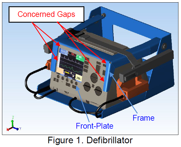
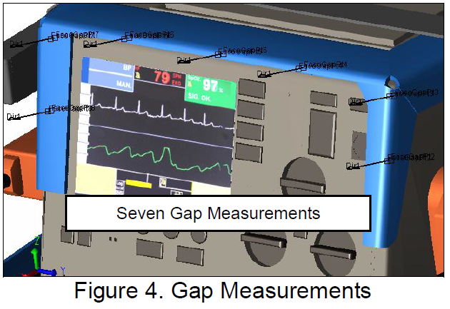
Given a medical Defibrillator device, as shown in Figure 1, the gaps between the Front-Plate and the Frame are the primary concern for final quality and ease of assembly.

Below we will build a variation model for the Defibrillator to evaluate the impact of various datum schemes. In this example, we limit our evaluation to the primary datum.
The goal is to find out which point among potential datum targets will produce the most robust design (smallest geometric factor) and the minimum variation (minimum deviation)?
1. Get the Nominal Components
2. Create Potential Datum Points
3. Create Measurements
4. Create Assembly Operations
5. Assign Tolerances
6. Performs Analysis
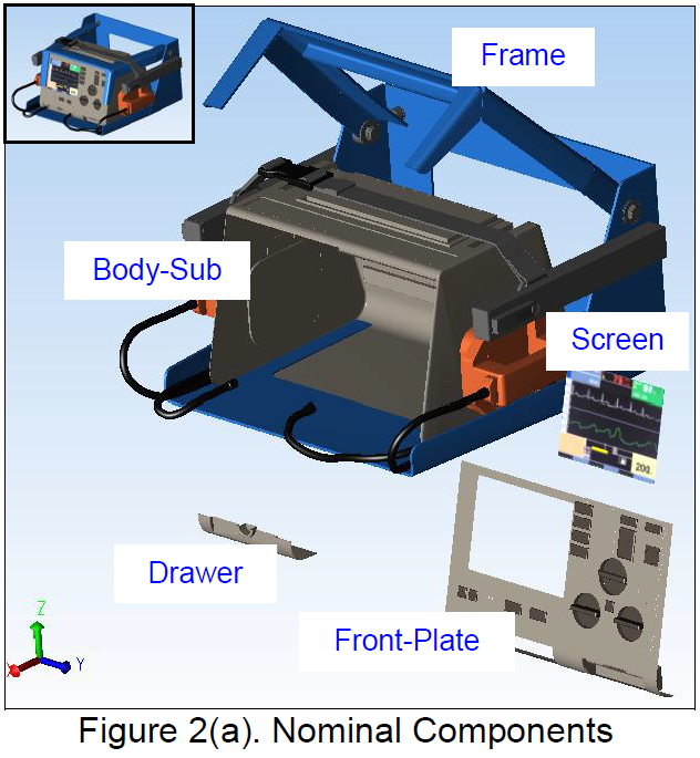
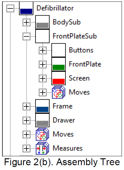
From your CAD model, bring in the nominally designed components, as shown in Figure 2(a). The assembly tree is shown in Figure 2(b). The Front-Plate sub-assembly consists of the Front-Plate and Screen.
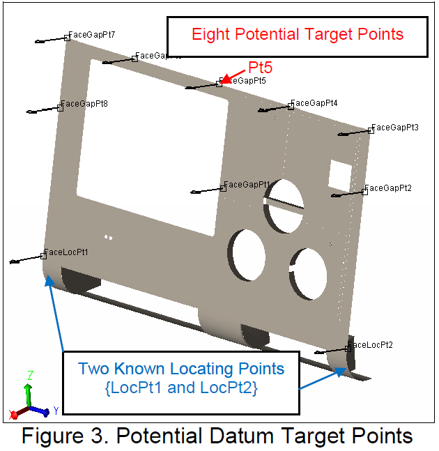
A set of points are created on the component Front-Plate, Figure 3. Among these points, two points {LocPt1 and LocPt2} are designated as known datum targets.
So, which point among the remaining eight candidate datum targets will produce the most robust design and minimum variation?
An analysis will determine the optimum position, but the model needs to be finished first to include the required inputs to be considered during analysis.
To control assembly quality, seven gap measurements will be taken around the face plate to quantify the variation, as shown in Figure 4. These will measure the flush condition of the face plate to the frame, and be used to check these points individual variation, as it will not be uniform across the surface.
3DCS uses Moves to assemble the product. To simplify the modeling details, Step-Plane Moves are used to build (1) Screen to Front-Plate; (2) Front-Plate to Body-Sub; (3) Drawer to Front-Plate; (4) Frame to Body-Sub. This is a simplified assembly process for ease of demonstration.
Since this model will serve for Datum evaluation, the most accurate tolerance information may not be available. We can assign tolerances based on historical data. In this example, all tolerances on the Front-Plate and Frame are set to 1.0. These can be created in 3DCS itself, or extracted from the CAD PMI (FTA in CATIA). In this case, as this example is studying design composition, it is assumed the CAD model is not yet complete, and so 3DCS tolerances are assigned in order to study possible outputs. This is common in early design phases, where a mix of industry experience (for example, known process tolerances based on ISO standards) and historical data are used to determine locating methods, critical areas and risk factors.
After the model is built with Moves, Tolerances and Measurements (MTM's), 3DCS is ready to produce simulation results. The variation results and geometric factors are generated with 3DCS Monte Carlo analysis and equation based solvers (Geofactor).
The analysis results were compiled into the following charts, shown in Figure 6(a-b).
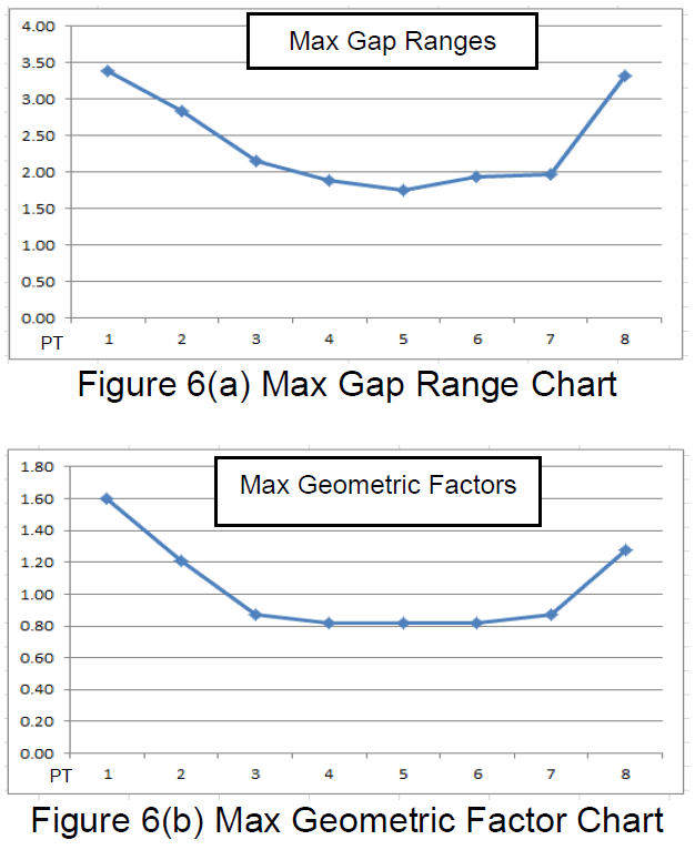
From Figure 6(a-b), we conclude that Pt5 is the most robust choice. As the third datum target, it will produce the minimum gap variation and the smallest geometric factor. This is consistent with the plane datum rule: Primary Datum Targets should cover the maximum area.
Running different analyses to test different methods will become even easier with the upcoming Version 7.6, which lets you create different model variants in the same model, turning on different locators, datum schemes, assembly processes or other MTM's to look at risk and analysis results.
- Download articles (DE Focus) on 3DCS methods, equations, special operations and applications.
- Watch Webinars On-Demand
- Read Frequently Asked Questions and use the search function to find answers
- Post questions to discuss with DCS engineers and other 3DCS and QDM Users


North American Innovation Center
28064 Center Oaks Ct A, Wixom, MI 48393
Call us: +1 (248) 504 6200


No Comments Yet
Let us know what you think