<img alt="" src="https://secure.smart-enterprise-365.com/779147.png" style="display:none;">

How to Simulate Material Thickness in 3DCS Tolerance Analysis

Nov 30, 2018 1:54:23 PM

 How to Better Treat Thickness Tolerances in Sheet-Like Materials

We encounter many situations where there is a form tolerance on a primary surface and then the other side of the part has a thickness allowance. Often implicitly it is assumed to have the same form or a very local refinement. (i.e. stamped sheet metal, composite lay-ups)There are many situations in both aerospace and automotive I would think where sheet of material is stamped and parts are indexed to both sides and sheet metal is accepted using a spec tolerance. 

One method used in the past has been to use ghost parts but it seems like there should be an easier way. What am i missing?

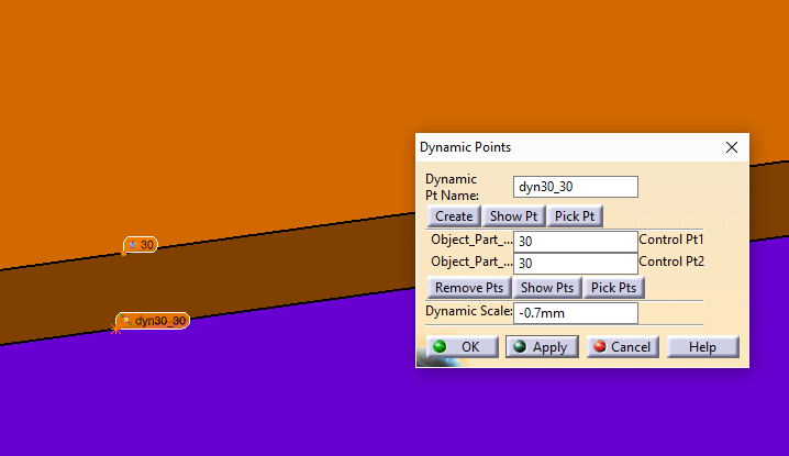
DCS has enhanced 3DCS software to handle many special case scenarios. To handle material thickness, for example, two methods would include using a Dynamic Point or Copy a Coordinate Point to reference thickness and then deviate the points with tolerances. Here is a guide to setting up analysis of material thickness in 3DCS software. 

3 Different Methods:

  • Dynamic Point
  • Copy Point from Thickness Offset
  • Copy Point Deviation DLL

Method 1 -- Dynamic Point:

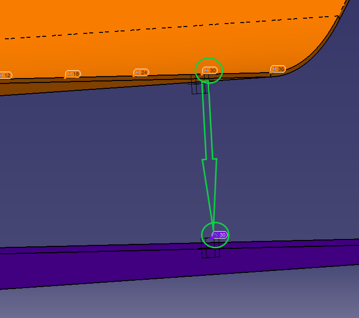
The Dynamic Point can be used as an offset point. Tolerances will need to be applied to the Feature Point or the Coordinate (DCS) Point.

  1. Create a new Dynamic Point, selecting the point to represent an offset twice.
  2. Set the Dynamic Scale to be the desired thickness (-0.25mm)
  3. Set the Dynamic Point in the move as the target point

Using the Dynamic Point as the Target point can be useful, as it will apply the tolerance variation to both the surface point and the Dynamic Point in the part, simulating the thickness.

sheet-metal-thickness-1-3dcs-tolerance-analysis

You can use this method to use the Dynamic Point as the Target Point in a move. You can still add tolerances to the surface or the Feature Point (Pt30), which will also cause the Dynamic Point to deviate with the surface tolerances.


Method 2 - Copy Point from Thickness Offset:

With this process, you’re basically taking the top surface point and copying that to the object part and using it as one of the locators in the move.

sheet-metal-thickness-2-3dcs-tolerance-analysis

You can use this method with your moves, to make the offset point (Object) to align to the target point. Then you can add tolerances to the Target point.


Method 3 - Copy Point Deviation (DLL)

This routine deviates the object features based on the deviation of the target features. The deviation includes both position and size with options. This routine is a move-deviating routine, which is deviating both positions and sizes associated with object features instead of moving the components (Move Parts.)

Inputs:

Object Features: At least one object feature is required.

Target Features: At least one target feature is required.

Values:

  • First Value: Position Scale - Can be positive, negative, or zero. When Position Scale is zero, no action is taken for the position deviation.
  • Second Value: Size Scale - Can be positive, negative, or zero. When Size Scale is zero, no action is taken for the size deviation.
  • Third Value: Target Calculation Flag - Can be 0 or 1. Indicates whether the target position and size should be combined or not. If Target Calculation Flag is zero (default), the target positions and sizes are averaged and applied on the object features. If Target Calculation Flag is 1, the target positions and sizes are applied by pairing each target and object feature with the same index.

Outputs:

  • The object feature position will be deviated by the target feature deviation with the Position-Scale if Position-Scale is non-zero.
  • The object size will be deviated by the target feature size deviation with the Size-Scale if Size-Scale is non-zero.
  • The routine only functions properly after the nominal build to get the correct target nominal positions and sizes.
  • If multiple target features are selected:
    • (1) When the target-calculation-flag is zero, the average values (position or size) are used.
    • (2) When the target-calculation-flag is 1, the deviation of target position and size will be applied on the paired object feature with the same index. If an object feature or a target feature is not a feature-of-size, the size deviation will be ignored.

Most DLLs have additional Options (Values/Constants) available. For the Copy Point Deviation DLL, it is suggested to set up the options as follows:

  • Value 1 = 1: Can be positive, negative, or zero. When Position Scale is zero, no action is taken for the position deviation.
    • Setting the option to 1 will set the tolerance type to Position.
  • Value 2 = 0: Size Scale - Can be positive, negative, or zero. When Size Scale is zero, no action is taken for the size deviation.
    • Setting to 0 will deactivate the option in the DLL to simulate the tolerance as Size.
  • Value 3 = 1: Target Calculation - If Target Calculation Flag is 1, the target positions and sizes are applied by pairing each target and object feature with the same index.

In summary, to simulate part thickness, there are a few ways to simulate this in a 3DCS model. Users can decide to use a DLL that will copy variation of points to another specific set of points or create and copy points to another part (not to a ghost part).

Learn more about modeling in 3DCS with the Digital GD&T Webinar Series - Iterative Logic and Iteration Moves - Dec 13th

digital-gdandt-webinar-series-2018

Subscribe by Email

No Comments Yet

Let us know what you think