Mechanical Modeler is an inexpensive add-on for all versions of 3DCS Variation Analyst Software
You can learn more about the Module here: https://www.3dcs.com/tolerance-analysis-software-and-spc-systems/add-ons/mechanical-modeler
3DCS Mechanical Modeler is an easy-to-use variation analysis solution for mechanical and kinematic assemblies. It provides a library of joints and constraints to model assembly processes beyond the 3-2-1 object-to-target method. Assemblies can be fixed or move through a range of motion. If the assembly moves through a range of motion, the Simulation results can be calculated at different steps along the motion. Over-constrained parts will be automatically accommodated.
The 3DCS Mechanical Modeler toolbar is located in the 3DCS Add-ons tab of the Menu ribbon. The ribbon with the expanded joints and constraints menu is shown below. The 3DCS Mechanical toolbar with expanded joints and constraints is shown below.

Moves differentiate between an Variation Analyst (standard 3DCS) model and a Mechanical model in 3DCS. With Standard Variation Analyst moves, the parts are fully constrained with no degrees of freedom remaining for motion. With Mechanical moves, degrees of freedom may remain available for motion. A single model may use a combination of both Analyst and Mechanical to simulate the assembly. The tolerances (or embedded GD&T PMI/FTA) and measurements used in a Mechanical model are the same as in a Variation Analyst model.
The library of Mechanical joint and constraint moves allows users to directly model the assembly process of mechanisms. For example, a four-bar linkage could be modeled with three revolute joint moves and one cylindrical joint move. 3DCS Mechanical will be able to validate functionality of mechanical systems such as suspension systems, engines, landing gear, doors, switches and other mechanisms.
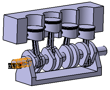
For this example, we will look at modeling a four cylinder internal combustion engine model composed of 11 parts: a Base, Block, Crankshaft, four Pistons, and four Rods. The parts will be assembled and animated based on mechanical joints and constraints. The final model will visually demonstrate a working mechanical model of an internal combustion engine.
The default location of the files used for this tutorial is: (Replace CAD with your system - NX, Creo, MultiCAD, CATIA)
Before starting, Learn more about:
Joints - https://blog.3dcs.com/joints-in-3dcs-how-to-use-cad-joints-in-3dcs-tolerance-analysis
Constraints - https://blog.3dcs.com/constraints-in-3dcs-how-to-use-cad-constraints-in-3dcs-tolerance-analysis
For a given attachment between parts, the user may be able to choose between multiple moves or multiple sets of moves. For example, a hinge could be modeled with a Revolute joint or with a Cylinder joint followed by a Planar joint.
When modeling, users should select joints first instead of constraints when possible. Joints are easier to validate and work better with (Kinematic) Motion moves. The joint moves do not include every possible type of attachment, however, so a typical model will include both types of moves.
Once a move is made, its Type can easily be changed.
Joints and constraints can act similar and have two main differences. The first difference is that a constraint will locate parts differently based on the types of features selected in a move. For example, a coincidence move with a hole and pin selected will locate them like a cylinder joint. A coincidence move with two planes selected will locate them like a planar joint. Joints are coded for just one type of feature. For example, a Planar joint with a hole and pin selected (not recommended) will attempt to locate them as though they were planes. The other main difference is that joints have Drop DOF set to No by default while most constraints have Drop DOF set to Yes by default.
The Drop DOF setting controls the method of trying to solve over-constrained systems. All the moves are used to generate a set of equations for the system. If Drop DOF is active for a move or set of moves, 3DCS searches through a set of cases (e.g. Plane,Plane, Plane; Plane, Axis, Axis; etc.) and finds the case that best represents the moves. It then uses the equations for that case to solve the model. Moves with drop DOF active are recommended for fully or over constrained parts because the locators should fit one of the cases. The over-constraining locators will be projected into planes so that the moves will always be solved. 3DCS has about 120 cases representing the most typical sets of locators. The move summary will tell you what case was chosen for debugging purposes. No list of the cases is available. If it is deemed no case represents the situation, a solver error will occur.
If Drop DOF is inactive for a move or set of moves, 3DCS generates equations based on the features and moves chosen. If the system is over-constrained 3DCS will keep dropping equations until it can be solved. If all the equations have to be dropped then a solver error will occur.
See also (for Mechanical FAQ): https://community.3dcs.com/viewforum.php?f=15
3DCS contains several types of mechanical joints to give users the ability to model a large range of assembly processes. This section divides move routines groups based on frequency of use and briefly defines the routines.
Click to Read: How to Use Joints in 3DCS
A chart summarizing the degrees of freedom controlled by each joint is shown below.
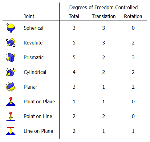
![]() Revolute locates two axes to one another, controlling four DoF's, and uses the plane constraints to control a fifth, translation, DoF (usually the tertiary locators).
Revolute locates two axes to one another, controlling four DoF's, and uses the plane constraints to control a fifth, translation, DoF (usually the tertiary locators).
![]() Cylindrical locates two axes to one another, controlling four DoF's.
Cylindrical locates two axes to one another, controlling four DoF's.
![]() Prismatic locates two axes to one another, controlling four DoF's, and uses the plane constraints to control a fifth, rotational DoF.
Prismatic locates two axes to one another, controlling four DoF's, and uses the plane constraints to control a fifth, rotational DoF.
![]() Spherical locates two spherical centers to one another, controlling three translation DoF's.
Spherical locates two spherical centers to one another, controlling three translation DoF's.
![]() Planar locates two features to be coplanar, controlling three DoF's (one translation and two rotation).
Planar locates two features to be coplanar, controlling three DoF's (one translation and two rotation).
![]() Point on Plane locates a point to a plane, controlling one DoF (one translation).
Point on Plane locates a point to a plane, controlling one DoF (one translation).
![]() Point on Line locates a point to an axis, controlling two DoF's (two translation).
Point on Line locates a point to an axis, controlling two DoF's (two translation).
![]() Line on Plane locates an axis to a plane, controlling two DoF's (one translation and one rotation).
Line on Plane locates an axis to a plane, controlling two DoF's (one translation and one rotation).
![]() Universal attaches two parts at their closest ends.
Universal attaches two parts at their closest ends.
Click to Read: How to Use Constraints in 3DCS
3DCS contains several types of part constraints to give users the ability to model a large range of assembly processes. The list of moves, however, can be confusing to a new user. This document divides move routines groups based on frequency of use and briefly defines the routines.
![]() Fixed holds all of the parts in the Move Parts list in their current location and orientation. Any moves that list one of the parts as the "object" will force the "target" part to move instead.
Fixed holds all of the parts in the Move Parts list in their current location and orientation. Any moves that list one of the parts as the "object" will force the "target" part to move instead.
![]() Fix Together holds all of the parts in the Move Parts list perfectly rigid relative to one another. If one of the parts is moved then the other parts will move with it.
Fix Together holds all of the parts in the Move Parts list perfectly rigid relative to one another. If one of the parts is moved then the other parts will move with it.
![]() Coincidence locates the features to be coplanar, coaxial or coincident.
Coincidence locates the features to be coplanar, coaxial or coincident.
![]() Contact locates the features so that their surfaces touch.
Contact locates the features so that their surfaces touch.
![]() Offset locates the features to be parallel (if applicable) and separated by an offset value.
Offset locates the features to be parallel (if applicable) and separated by an offset value.
![]() Angle locates the features to be rotated apart from one another so that the angle between then is the specified value.
Angle locates the features to be rotated apart from one another so that the angle between then is the specified value.
In addition to joints and constraints, 3DCS Mechanical provides a graphical representation of the motion of an assembly with kinematics options. Creating a Kinematic Motion move will step the assembly through a range of motion while maintaining the other constraints and joints in the model.
These options allow the impact of motion to be visualized with Kinematic Animation and measured with the Kinematic Simulation.
![]() Kinematic Simulation repeats the analysis at each step of the Kinematic Motion move during Simulation.
Kinematic Simulation repeats the analysis at each step of the Kinematic Motion move during Simulation.
![]() Kinematic Animation graphically animates the selected Kinematic Motion move.
Kinematic Animation graphically animates the selected Kinematic Motion move.
![]() Kinematic Motion rotates or translates a part while maintaining the other joint and constraints allowing the assembly to be analyzed at various positions.
Kinematic Motion rotates or translates a part while maintaining the other joint and constraints allowing the assembly to be analyzed at various positions.
The ![]() Kinematic Simulation function repeats the Simulation analysis at each step of the selected kinematic motion move.
Kinematic Simulation function repeats the Simulation analysis at each step of the selected kinematic motion move.

The following fields can be modified based on user requirements.
Motion Selection:
Total Runs:
Initial Seed:
Total Measures:
Browse ![]() :
:
Start:
Close:
Mechanical Outputs
After the simulation has finished, it will save and open a .csv file containing statistical results for each step from the Kinematic Motion move.
![]()
Notes:
Running an Analysis Simulation is also possible with Mechanical. Please take note of the following settings
The ![]() Kinematic Animation graphically animates the selected kinematic motion move. This function is used after Nominal Build.
Kinematic Animation graphically animates the selected kinematic motion move. This function is used after Nominal Build.
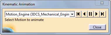
The following options help to navigate through the steps of a kinematic motion move.
Motion List: This pull-down menu allows the user to select the motion move to animate. Only one motion move can selected at a time.
Animation Commands:
![]() Performs one step of the motion move per click of the button (forward and reverse).
Performs one step of the motion move per click of the button (forward and reverse).
![]() Increments through all the steps of the motion move (forward and reverse).
Increments through all the steps of the motion move (forward and reverse).
![]() Pauses the motion move.
Pauses the motion move.
Kinematic Motion:
The ![]() Kinematic Motion Move rotates or translates a part while maintaining the other joint and constraints, allowing the assembly to be analyzed at various positions. This move works in conjunction with the Kinematic Simulation and Kinematic Animation routines. Using Run Analysis, GeoFactor, or Advanced Analyzer Optimizer AAO on a model with motion moves will run each analysis with the motion moves at their first step. The motion moves are not activated during Nominal Build.
Kinematic Motion Move rotates or translates a part while maintaining the other joint and constraints, allowing the assembly to be analyzed at various positions. This move works in conjunction with the Kinematic Simulation and Kinematic Animation routines. Using Run Analysis, GeoFactor, or Advanced Analyzer Optimizer AAO on a model with motion moves will run each analysis with the motion moves at their first step. The motion moves are not activated during Nominal Build.

Motion Specification:
The steps of the motion are specified in this tab. First, choose a type of motion out of the four different actions specified in the drop-down menu. Depending on the type of move, the user can specify and start and end position of the assembly and how many steps the motion is divided into.

Joint Type:
Motion Steps: The number of steps the translation or rotation will be divided into.
Motion Beginning Pos: With "Comp" motion types, this is the first value stepped to.
Motion End Pos: With "Comp" motion types, this is the last value stepped to.
Defined Motion Steps: With "By Steps" motion types, add the values to be stepped to from this list.
Model kinematics allows the user to translate or rotate parts while maintaining defined constraints and joints to model the motion of an assembly. The motion definition can be modified based on cycle parameters.
STEP 1 Motion Tab:
Choose the Motion Type from the drop-down menu.
Based on whether the 'Comp' or 'By Steps' method is chosen, specify the start/end point of motion and the step size or the values to step the motion to.
STEP 2 Feature Tab:
Click in the white box of Center of Rotation and select the feature or axis about which the assembly will be rotated. If translating parts, this field is not needed.
Click in the white box of Direction and select a feature or axis about which the assembly will rotate in the graphics window (it can be the same as the other field.) If translating parts, select a feature or axis about which the assembly will translate along.
For example, the end of the crankshaft was chosen as both the Center of Rotation and Direction below.
STEP 3 Move Parts Tab:
Select the part or parts that will be moved the exact amount specified by the motion. In the engine above, only the crankshaft should be selected. The other moves will cause the rods and pistons to move with it. If a second part is listed, then the first part will be moved relative to the second part.
This allows both parts to be moved later as a rigid sub-assembly.
STEP 4 Settings Tab:
Update settings as desired.
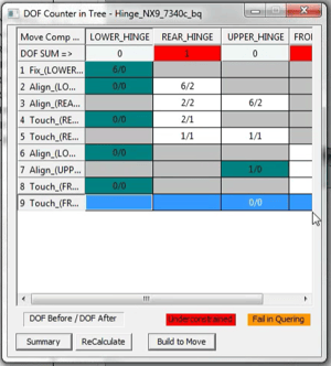
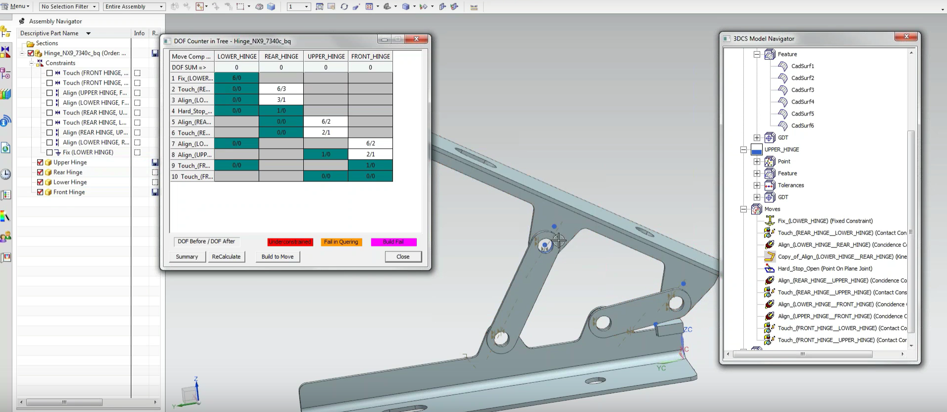
3DCS Mechanical Modeler can extract the Joints and Constraints from a CAD model, especially when using the integrated versions of 3DCS (CATIA, NX UG). These are applied to the model as DCS Moves. When used in conjunction with embedded GD&T (FT&A or PMI), a user can essentially build an entire 3DCS model in minutes.
The Degree of Freedom Counter can then be used to check your moves to make sure all of your parts are properly constrained and that your moves are set up correctly. If they are not, add moves to constrain additional degrees of freedom and run your analysis.
Like all the DCS Webinars, this one is FREE and open to all registrants.


North American Innovation Center
28064 Center Oaks Ct A, Wixom, MI 48393
Call us: +1 (248) 504 6200


No Comments Yet
Let us know what you think