DCS is proud to be presenting alongside Bordrin New Energy Vehicle Company Senior Advanced Manufacturing Engineer Vince Radziecki Thursday, December 12th at 11 am EST via Gotowebinar -
DCS teaches the basic fundamentals of a 3DCS model during basic training. These fundamentals, however, often assume that the modeler has already done some work beforehand to determine important objectives and processes for the model. What do we mean by this?
When modeling in 3DCS, in order to get the best outputs, you need to have all the inputs. This includes understanding what you want your outputs to be: where you need to focus your studies, which areas you want to measure, and what questions you're trying to answer. As part of this, it is key to understand how the parts locate and assemble to one another, so that tooling, Datums, and locators can all be modeled that properly represent how the product will be assembled at the plant. This development of the Digital Twin is only truly effective if the information is reflective of the actual parts and product information.
 . Knowing how parts locate and assemble before beginning a model is key
Therefore, before even beginning a model, there are some very helpful steps that should take place.
This webinar will discuss these steps, and Vince Radziecki, Senior Advanced Manufacturing Engineer at Bordrin New Energy Vehicle Company, will demonstrate examples and a Case Study demonstrating the early steps that make modeling not only easier, but more effective. In addition, he will be showcasing the modeling process itself following a component through the entire process from start to finish.
-- Receiving a new model (initial actions)
-- Determine Outputs/Measurements
-- Setting up the model
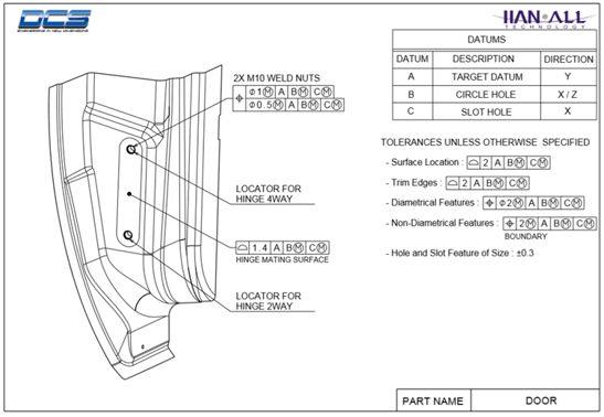
-- GD&T - DATUM Structure
-- Understanding the Assembly Process
-- Building the Model
Before the webinar, let's review the modeling method from the DCS Help Manual.
There has been a lot of discussion about "Bottom Up" and "Top Down" modeling. 3DCS can support both strategies depending on the project. The project managers will determine what method you should follow. Here is a brief summary of the two techniques.
The "Bottom Up" or "Piece Part" modeling philosophy focuses on creating and verifying the Tolerances to the GD&T first. The Moves can be created next and verified to ensure that the model reflects the manufacturing process. The Measurements could then be created last and can be added anywhere in the validated model to determine if the Objective of the model was met.
The "Top Down" or "Black Box" modeling philosophy tends to focus on creating and checking the Measurements first and verifying the correct Objective Pt locations. The Model is based on sub-assembly locators and datums rather than piece parts. The Moves can be created next and verified to ensure that the model reflects the manufacturing process. Additional Moves may be created for alternate schemes (What-if's) to support robust concept selection. The Tolerances can be generic because the allocation process will determine the GD&T tolerance needed to meet the Objective.
The "Top Down" approach would involve creating 3-D models from x,y,z coordinates or from clay scans. Models can be generated from minimal math data to look at different strategies for process. When CAD data is complete it can be merged in with the original model. The model does not have to be regenerated when new data updates are available.
Models can also be generated by using concept model libraries for modeling common areas of the vehicle.
When creating a 3DCS model, the Help Manual recommends a number of steps before even loading the model in your CAD system. These steps are often understated, and yet, they often determine the method and scope of the model. As you can see in the modeling steps below, identifying the specifications of the Build Objectives and measurements and then identifying fixtures, gages as well as assemblies and components, there are important steps that set the method of the entire modeling process that are done outside of CAD.
Let's review what comprises a 3DCS model itself.
The basic requirement of a model is the creation of part geometry. All part components that are analyzed have to be defined in the model. This is done by keying-in their X,Y and Z coordinates to define geometry elements like DCS Points, and Circles. Another method of creating geometry is by obtaining AD information through an AGES file, which can be directly imported into the software. This saves the time involved in keying-in the part's coordinates.
This information is essential as it defines how the part geometry sequentially goes together in an assembly. Within 3DCS Variation Analyst, a Move defines how one part locates to another. Since each part has unique locators, appropriate Moves have to be selected to assemble different parts together. Many Moves must be defined to build an entire assembly. The Move choices are available in 3DCS Variation Analyst.
The 3DCS Variation Analyst model is built and simulated to study the effects of tolerances in an assembly. Hence, tolerances are of great significance in a model. Proper definition and application of tolerances to appropriate areas of the model are required.
To understand the effects of tolerances in a model, measurements are defined in suitable areas of the model. These measurements describe the variation induced in different areas of an assembly, caused by the parts in that assembly.
The time necessary for 3DCS Variation Analyst to perform a simulation analysis varies, depending on several factors including the number of simulated builds (Runs), size of the assembly, distributions, hardware capability, etc.
1. Modifying the assembly:
2. Applying the Assembly Process:
3. Defining Tolerances:
4. Build Objectives
5. Results
6. Report the Results


North American Innovation Center
28064 Center Oaks Ct A, Wixom, MI 48393
Call us: +1 (248) 504 6200


No Comments Yet
Let us know what you think