 This article compiles information about the Iteration Move in 3DCS to help you use it and apply it in your tolerance analysis modeling. For more about Iteration Move, visit the DCS Community at:
https://community.3dcs.com/help_manual/iterationmove.htm?zoom_highlightsub=iteration+move
https://community.3dcs.com/help_manual/dcu_loopmv_dll.htm?zoom_highlightsub=iteration+move
The Iteration Move is required when an object is to be rotated about a center point in small increments, translated in small increments in a particular direction, or when constructing loop logic around a series of moves. The move will iterate until a measurement is within a specified range.
Some applications for the Iteration Move include Suspensions, Hinges and Linkages.
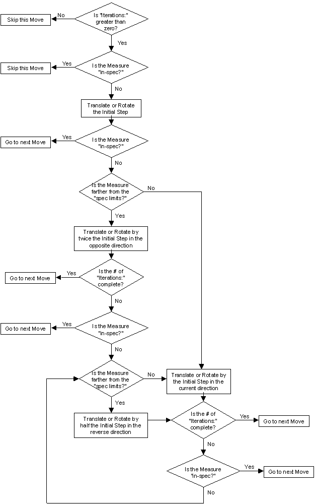
Flow Diagram of Internal Logic
Creating:
Selecting Iteration Move displays the Iteration Move dialog box along with the part name.
Move Objects Definition:
Click the Add button under to Move Parts and select the parts to move from the parts tree or from the graphics area. There is no limitation for the number of parts in the list. Click on Close when done to return to the Iteration Move dialog box. A Key In Part Name field lets you type in the name of the part in order to select it. The list box under Move objects displays the names of all the parts selected.
To Delete any part, highlight the part in the list box and select the Delete button.
When the Iteration move is used to model relative movement in an assembly of parts, such as calibrating a series of parts by adjusting a set screw, only one part (such as the set screw) should be chosen. The other parts must be adjusted by the moves embedded in the loop.
Translate/Rotate:
From the Mode drop-down list, choose either Translate or Rotate to define how the selected Move Objects have to move in order to satisfy the Iteration Move condition. Note: This setting is not required if no parts are selected.
Initial Step:
Enter the initial step value by which the move objects have to be either translated or rotated incrementally. In general, a larger initial step will let the model build faster.
Max Move Num:
Max Move Num specifies the number of Moves after the Iteration Move to be included in the loop and performed in each loop iteration. It does not include the Iteration Move itself. These Moves must appear immediately after the Iteration Move in the move list, and they will be performed if the Move is Active or Inactive. If you do not wish to have these moves performed again after the Iteration loop has stopped iterating, make the moves Inactive.
On each pass through the loop of an iteration move, the specified interference condition is checked, and if not satisfied, all moves are performed again. The interference condition check is a Measure which is specified in the Options dialog of this move. The Default Max Move Num is now 0, new in 6.3.0
Center:
If Rotate was selected, click on the Center Pt. button to select the center point about which the Move objects will be rotated. The point name, along with the part it belongs to, is displayed next to the center button.
Direction:
When Translate is selected, the vector entered in the Direction area defines the direction of movement. When Rotate is selected, the vector entered in the Direction area defines the axis of rotation about the center point. The right hand rule applies for the first iteration rotation. If the part moved in a direction that moves the value of the measurement farther from the spec limits, the direction of rotation/translation will reverse in the next iteration.
Options:
The Options button brings up the Options dialog box which contains settings for conditional logic and Iterative logic. In the Iterative Logic area, specify the measure to check each loop through the iterative logic. If the Interference Measure is out of specification, and the number of Iterations specified has not been reached, the iterative loop will be performed again.
The Search Accuracy is the minimum value that the step size will be reduced to before the Move stops iterating. Note: A measurement must be selected in the Interference section of the Move Options.
If the number of times is 0 or the measured value is within spec, nothing is done.
If the measured value is out of spec the part is translated or rotated by the amount in the Initial Step field, and moves indicated by the Max Move Number are looped through.
If the number of iterations completed is equal to the number in the Times= box or the measured value is within spec, the loop stops.
If the measured value is smaller than in the previous pass, the part is moved the same increment in the same direction.
If the measured value is larger than in the previous pass, the part is moved the ½ of the previous increment in the opposite direction.
In either case, the moves including in the loop are performed.
Note:
STEP 1. Consider the only Move part is a line to be translated in the specified vector direction.

The line is translated in small linear increments in the specified direction.

STEP 2. The object line will keep translating in linear increments until the interference Measurement condition that has to be met is satisfied.
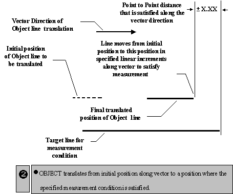
Note: If the number of iterations needed to translate the part so that the measurement is within the design limits is not enough, the part may not be moved to the proper position. Leave the measure As Output to verify. Also, use the Continuous Deviate feature to verify.
STEP 1. Consider a line as the object part to be rotated about a center point with an axis in the direction of the specified vector.
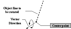
The line rotates in small angular increments in a direction normal to the specified vector.
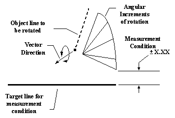
STEP 2. The object line keeps rotating in increments until the measurement condition that has to be met is satisfied.
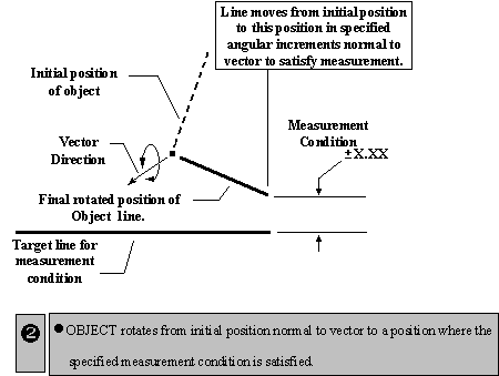
Note: If the number of Iterations needed to rotate the part so that the measurement is within the design limits is not enough, the part will not be rotated to the proper position. Leave the measure As Output to verify. Also, use the Continuous Deviate feature to verify.
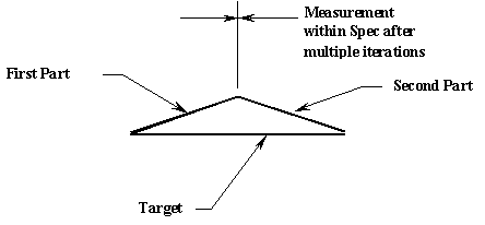
STEP 1. Consider two lines which are to be moved to a base at the bottom and rotated towards each other at the top. The Iteration Move is not used to move any parts, but only used to repeat the following two moves (defined in Max Move Num:) until the Interference Measurement (the distance between the two top object points) is within its design limits. The Iteration Move will perform the two Moves following the Iteration Move whether they are checked as active or inactive.
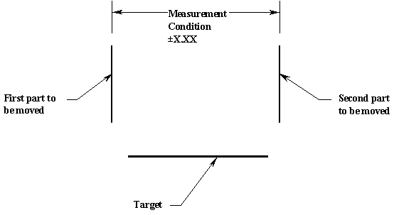
A check is made before any Moves are performed. If the Interference Measurement is within spec, no moves will be performed.
STEP 2. If the measurement is outside of the design limits and the iteration value is greater than 0, the number of moves shown in the Max Move Num box will be performed repeatedly until the parts are within spec or the number of iterations completed is equal to the value in the "Times" edit box.
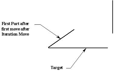
The first move is performed.
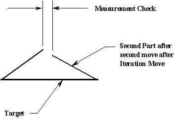
The second move is performed.
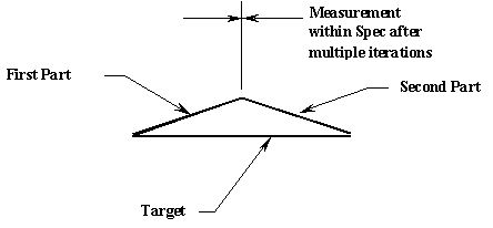
The moves are repeatedly performed until the parts are within spec.
Note: If the number of iterations needed to translate the part so that the measurement is within the design limits is not enough, the part may not be moved to the proper position. Leave the measure As Output to verify. Also, use the Continuous Deviate feature to verify.
SPECIAL NOTES:
Click below to view the recorded session, demonstrating the Iteration Move and Mechanical Kinematic Moves.

These Stories on CATIA
No Comments Yet
Let us know what you think