Authors and Contributors:
Zheng, Hanchen (1) [primary author]; Litwa, Frank (1); Reese, Benjamin (2); Li, Chenyang (2); Bohn, Martin (1);
Paetzold, Kristin (3)
1: Daimler AG; 2: Dimensional Control Systems Inc.; 3: Universität der Bundeswehr München
Computer aided tolerancing (CAT) in the automobile industry is implemented by CAD tools. These
tools analyze the manufacturability of complex assemblies with rigid single parts in an early stage to
reduce the product development time and the cost for hardware prototypes. This paper proposes an approach to implement tolerance simulation for a compliant assembly, which includes manufacturing processes such as clinching, bolting and hemming by applying tolerance simulation tool. The fender- BIW system is simulated as a compliant–rigid system and the simulation model is applied to two production scenarios. The simulation results are compared with real measurement data, which demonstrates the efficacy of using simulation in early production as opposed to prototyping or other methods of design by showing the strong correlation between simulation results and as-built products.
These clips from the article can help you get an idea of the purpose and information in the paper. To see the complete work, use the link above or at the bottom to get FREE access to the whitepaper.
Currently, computer aided tolerancing (CAT) in the automobile industry is implemented by digital tools. These tools analyze the manufacturability of complex assemblies in an early stage to reduce the product development time and the cost for hardware prototypes. Camelio and Hu (2003) summarized the propagation of variation analysis models from single station to multi-station for rigid parts. He also proposed a modeling methodology to simulate the multi-station assembly process of a compliant sidewall of automobile. Schleich and Wartzack (2016) summarized the major approaches applied regarding the rigid mechanical assemblies. Corrado and Polini (2017) presented a general method to integrate the manufacturing signature and the assembly conditions into the existing theoretical models of tolerance analysis for rigid parts. At the same time, the finite element method (FEM) was also applied in the tolerance analysis. For example, Liu and Hu (1997) developed the method of influence coefficient (MIC) to simulate compliant sheet metal assemblies, Chang and Grssard (1997) proposed PCFR (Positioning, Clamping, Fastening and Releasing) cycle to model the assembly of compliant parts, butt joint and a slip joint in a body in white (BIW) process are analyzed in the work of Moos and Vezzetti (2012).
However, the conventional statistical tolerance simulation results has a shortage in fitting to the real
manufacturing processes. The rigid tolerance simulation ignores any deformation in the parts, which
can be caused by clamping, welding, clinching, riveting or other over-constraining operations. FEM
simulation is capable of simulating the compliant part, but the simulation model must be modified for each case and the length of the simulation run time scales with model size and complexity.
* * * See Complete Paper for the rest of the introduction * * *
The assembly process of BIW hang-on parts is a multi-station process (including clinching process
and hemming process). Both mentioned CAT tools provide the ability to simulate the compliant
assembly process virtually. 3DCS FEA Compliant Modeler is developed mainly based on the method
proposed by Camelio (2004). For a sheet metal assembly system with geometric co-variance and large number of variation sources, it substantially reduces the computational effort comparing to VisVSA (developed based on MIC). Therefore, the elastic tolerance simulation in this paper is implemented by using 3DCS FEA Compliant Modeler.
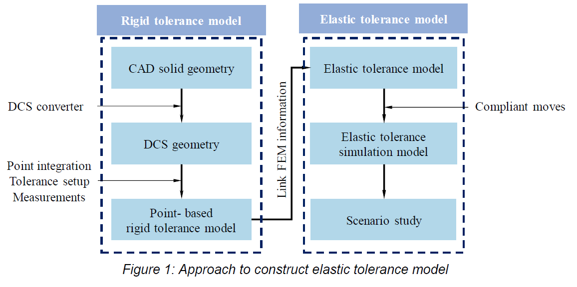
An approach to implement the elastic tolerance modeling using 3DCS is introduced in Figure 1. The CAD solid geometry of the assembly (exported from NX) can be imported into 3DCS with the DCS converter. After importing, DCS points can be defined by typing in the coordinates and normal vector, or directly inserting at the geometry surface to create a point-based rigid simulation model. Tolerances and measurements are defined according to the user’s specification. After combining the FEM information with the tolerance model, many manufacturing processes can be simulated by utilizing the compliant moves according to the assembly sequence. The general procedures for using 3DCS are specified in the user guidelines (Dimensional Control System, 2008), but the modeling approach needs to be adjusted for specific simulation systems.
* * * See complete paper for complete tolerance process * * *
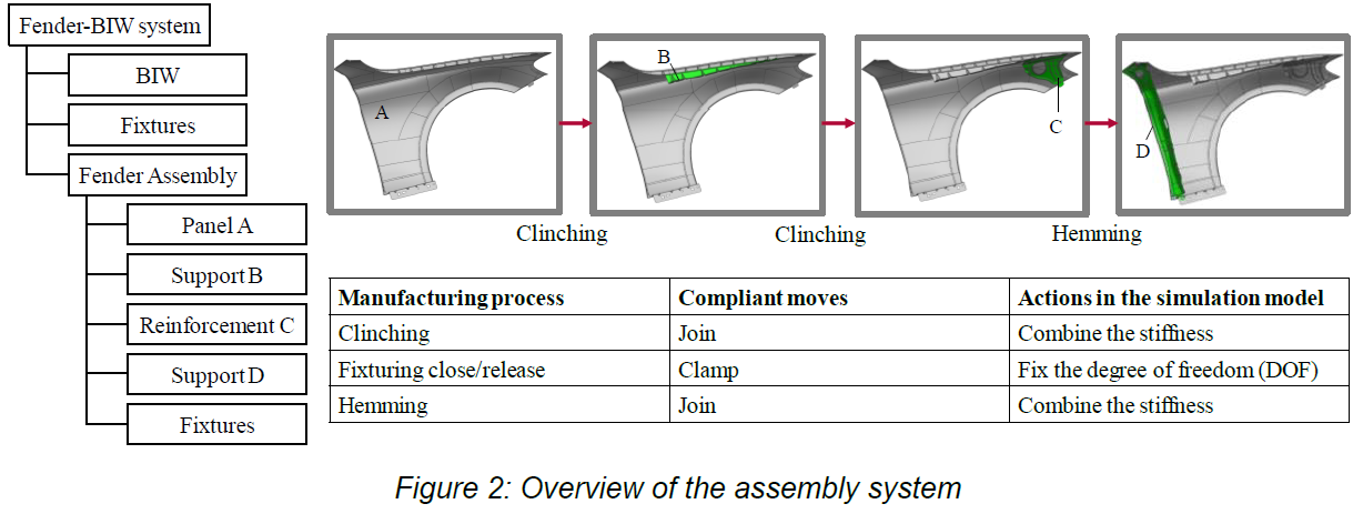
Figure 2 is an overview of the fender-BIW system. The fender assembly consists of four compliant
components: a panel (A), two supports (B and D) and a reinforcement (C). Because the elastic
behavior of the fender assembly due to manufacturing processes is studied in this paper, the
deformations of the BIW and the fixtures are neglected as a simplification of the system. Therefore,
the BIW as well as the fixtures in the system are assumed as a rigid “Black box”, which deviates at the
joining positions with the fender assembly according to tolerances specification. Following are the
modeling procedures for the manufacturing process of the fender:
...(see complete paper)
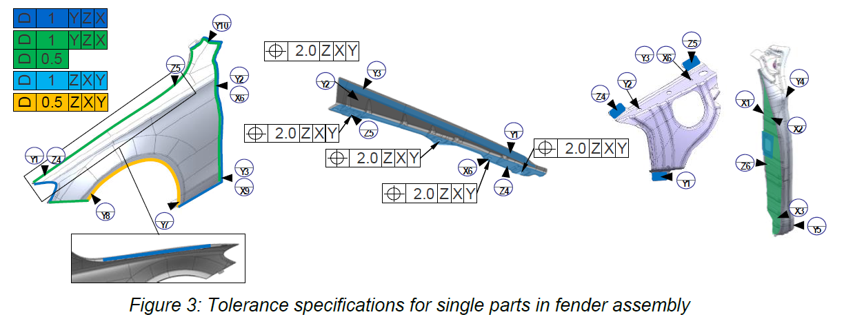
The tolerances used in the simulation model are specified according to the tolerance specification
given by Daimler AG for the specific parts (Figure 3) which based on Reference-Point-System (RPS).
The difference between Daimler tolerance specification and ISO tolerancing standard are discussed in the work of Yan (2019). Linear tolerances are defined on the corresponding DCS points referring to their references. Circle tolerances are defined at all pin-hole joints and bolting positions to simulate position tolerances as well as size tolerances. The tolerances for fixtures are defined at the DCS points that are fixed on the fixtures. Normal distribution is selected for all tolerances.
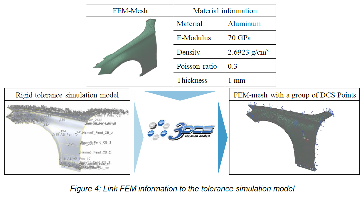
The rigid-body tolerance model becomes an elastic tolerance model when the FEM information is
loaded. In this model, all parts are made of aluminum with a thickness of 1 mm. The material
information is listed in Figure 4.
Figure 4 also indicates the process of linking FEM data to the tolerance simulation model. The DCS
points on the fender are integrated with the FEM-mesh. The nodes nearest to the DCS points are
grouped in the FEM model. The reduced stiffness matrix file for every compliant part is generated
with the FEA tool. After the new FEM-mesh and reduced stiffness matrix are generated, the function
“Load FEA data” in 3DCS Compliant Modeler links them to the simulation model so that the rigid
model becomes compliant.

The manufacturing processes of the fender consist of two stations. The first station assembles the
individual components A, B, C and D together. As shown in Figure 2, the panel A and the support B
are fixed on the fixtures before they are clinched together. The sub-assembly AB is released and shifted to the next joint process. The sub-assembly AB and the reinforcement C are then fixed on fixtures and clinched together. Finally, the support D is fixed at the proper position and hemmed with the sub-assembly ABC to form the fender assembly. During this joint process, the flanges of A and D are assumed to be firmly connected; the non-linear effect due to the glue between parts is not considered in this paper, so no relative sliding occurs at the contact interfaces during the hemming process.
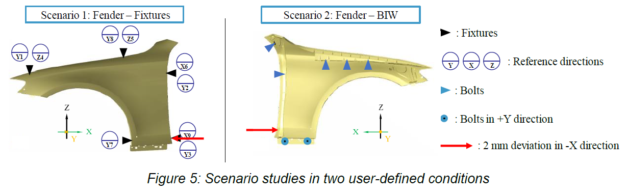
Finally, the fender assembly is released from the fixtures and shifted to the next station for the
mounting process. At the second station, the fender assembly is mounted to the BIW at the positions shown in scenario 2, Figure 5. Because the BIW is considered a rigid body in the simulation model, a clamp move is used here to bolt the fender to DCS points of BIW at the bolting position.
* * * See complete paper to learn more * * *
Hanchen Zheng included his process, results, and conclusion in the paper, showcasing his findings and recommendations. If you'd like to see those, use the link below to download the complete whitepaper FREE


North American Innovation Center
28064 Center Oaks Ct A, Wixom, MI 48393
Call us: +1 (248) 504 6200


No Comments Yet
Let us know what you think