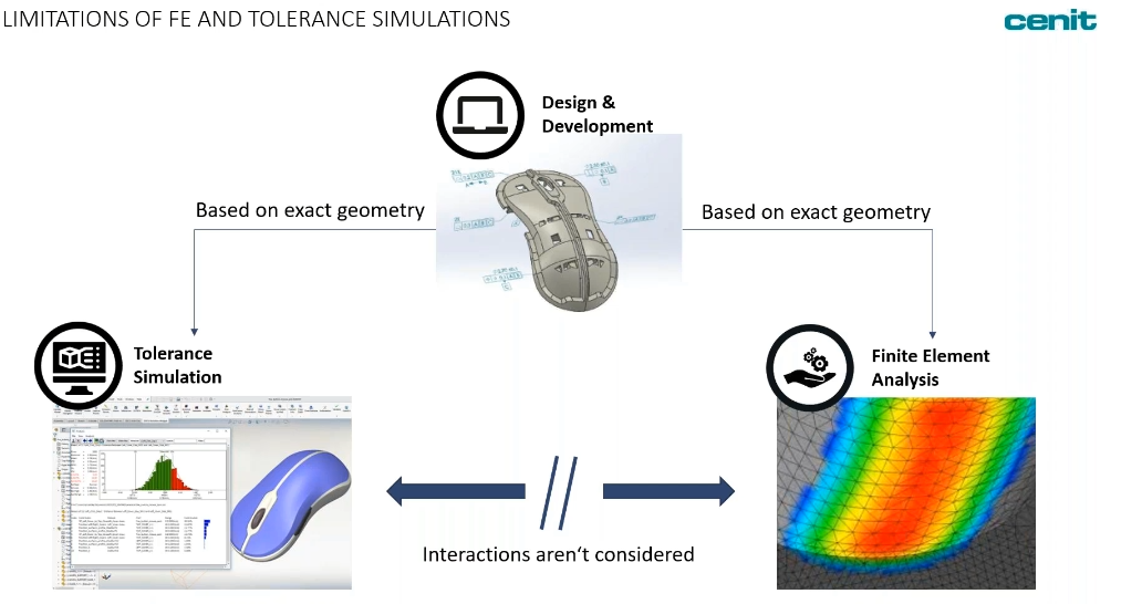

In manufacturing, Finite Element Analysis is now a standard part of most design processes. In the same regard, it is understood that some tolerance stack analysis needs to take place in order to understand the impact of variation and account for it. These two analyses are often done in parallel in different software packages, and then the results are combined afterward to understand the two together. This is both difficult and time-consuming.
We'd like to change that.

The goal here is to combine the Finite Element Analysis (FEA) and tolerance simulation into a single analysis, and single software package, find a common result and then provide that back to the design team.
To showcase this process, DCS partner CENIT has created an example that highlights the simpler method for use by the CAD design team early in the digital phase of production. More advanced methods are available as well, and we will be showcasing those at a later webinar event. (In the meantime, you can see some by clicking here).
The idea is to show how to combine both worlds; FEA and tolerance simulation, such that you get more insight into your processes much sooner. We know that simulation of any kind relies on what design inputs go into it. This provides some limitations:
1. Have to base it on the CAD data - this is assumed to be perfect, with no displacement or variation.
2. Based on perfect geometry and conditions.
If you understand manufacturing, you already know that no part is produced perfectly to design and that the conditions - temperature, processes, material - are never perfect. If you don't have perfect geometry, you need to know how it deviates from nominal and what the effects will be on your assembly.
FEA results may interact with tolerance simulation, but the link is usually hard to create. It is usually too much work to combine the disciplines as the software packages rarely get along.
In this webinar, we would like to show you how to do this on the level of a designer, rather than an expert.
How can the FEA results help in your tolerance simulation?
There are a lot of answers, so here are some examples:
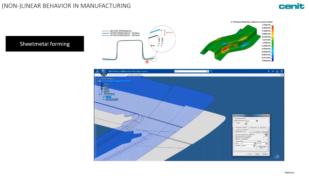
Large sheet metal structures are shaped by hydraulic presses. When doing so, the material gets elastic deformations that remain in the system. The elastic energy in the system deforms the geometry as soon as the press is removed. This effect is called Spingback, and due to its presence, you will see many slight deviations from your desired geometry. What's more, the larger the part, the larger the effect.
In addition to Springback, the unequal pressure of the press may cause a difference in material thickness. This can create thinner or thicker zones on the part that then react differently to later processes, causing additional variation.
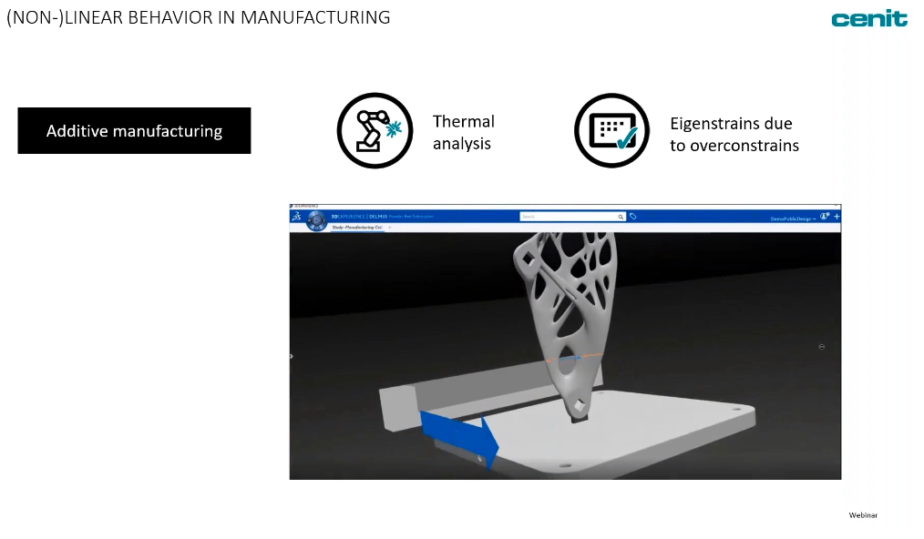
It's no surprise that additive manufacturing has problems with thermal effects. In most additive processes, material is heated as it is delivered in order to form the parts. This heat can deform the material, and not just the new material, but also the previous layers of material on the part, causing deformations. Of course, the material has to cool down, and the cooling process may be unequal, causing additional deformation.
Additionally, when created in a machine, the parts for additive manufacturing are often overconstrained. Once released, the parts will have some changes.
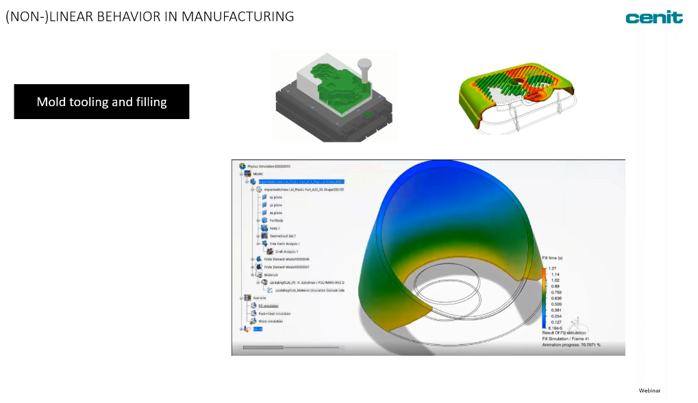
Plastic injection molding - in these production processes, temperature plays a powerful role. Filling the mold and the temperature of the system can cause deviations from unequal cooling, improper filling, and the distribution of heat across the system.
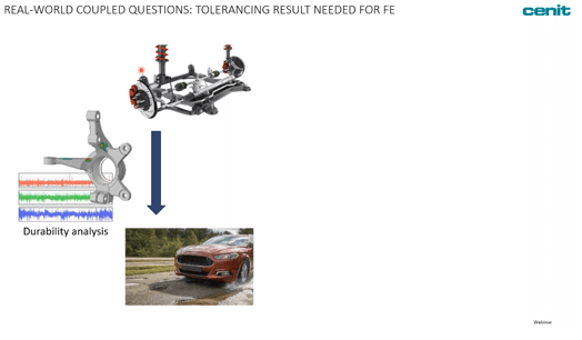
Steering Linkage (to be shown in a future webinar, we only have 1 hour...)
How does the tolerance result interact with the finite element results? In this example, the steering linkage is being investigated for durability over a bumpy road. With load cycles swiftly changing, as well as harmonic oscillations. You want to know when and where the part will fail on the cyclic loading. This is common in FEA, however, the variation may change exactly where the stresses are going to occur, completely changing your expected results.
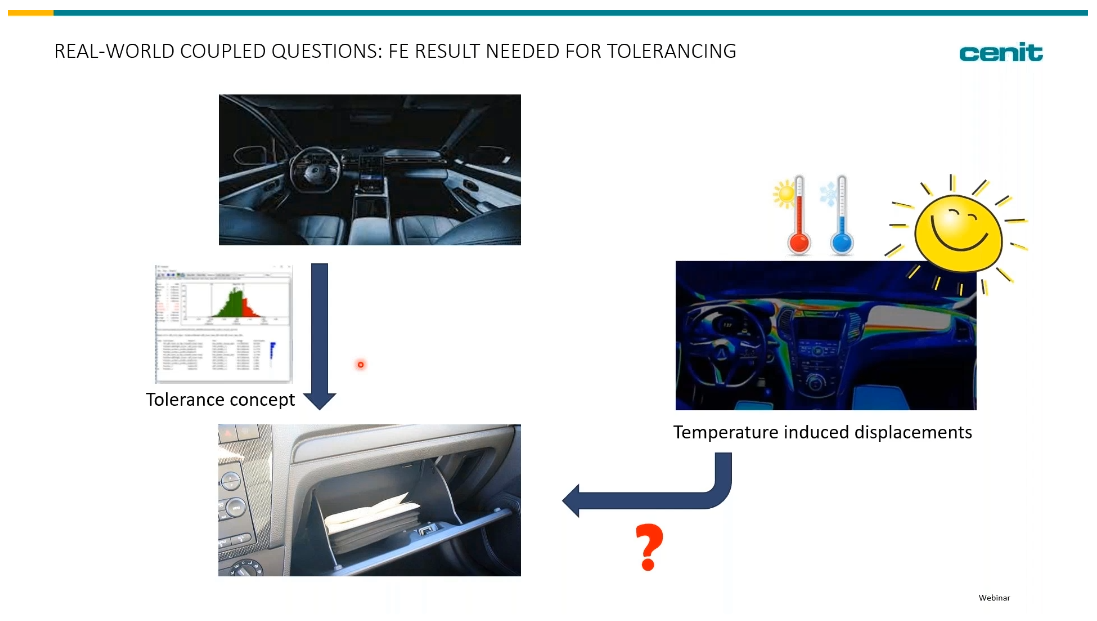
Automotive Interior - Material Deformation from Plastic Components (Example to be shown)
How does the FEA interact with the tolerance simulation on the car interior. The car may sit in the sun and the material heat up to much higher temperatures, and then during colder months, drop to much lower temperatures. The swelling and shrinking of material will affect the gaps and connections between components. This analysis needs to answer, if my parts deform from temperature, will my parts still function and look correctly? (you can see the appearance portion in our previous webinar here looking at Perceived Quality).
Join CENIT and DCS on April 27th to See First Hand How These Two Disciplines can be Combined Into a Single Analysis


North American Innovation Center
28064 Center Oaks Ct A, Wixom, MI 48393
Call us: +1 (248) 504 6200


No Comments Yet
Let us know what you think