 Enhanced Scenes
Customizing Your Assembly in CATIA V5 and 3DCS
Enhanced Scenes allow you to customize the configuration of your model at nominal and exploded view. This can be helpful when modeling assembly processes or checking your work.
Introduction
An Enhanced Scene in CATIA V5 is a set of positions for an assembly. This helpful tool in CATIA works alongside 3DCS, creating the assembly at a nominal starting position or defining an exploded position for a 3DCS model.
This Tips and Tactics will explain how to create a Scene in CATIA V5 and the benefits of using Scenes with a 3DCS model.
Making a Scene in CATIA V5
 Begin by opening a new model.
- Switch the workbench in CATIA to Assembly Design, if not already active.
- Select Enhanced Scene on the Scenes Toolbar
- Naming: You can decide to specify a name for a Scene, for example: Translated Position, or allow CATIA V5 to create a generic name
- Automatic naming: CATIA will create a generic name: Scene_1
- Deactivating Automatic Naming will give the user the ability to name the Scene
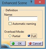 Overload Mode: This option allows the user to create a scene with just the translated parts or the entire assembly.
- Partial: Will only take parts that have been translated or positioned differently from their nominal or design position
- Full: Will take each part in the assembly
- Once the window switches, exit the scene. Exiting the Scene will create the Scene in CATIA V5. Otherwise, this will give you another chance to modify the position of the parts within the scene itself.
Swapping between Scenes
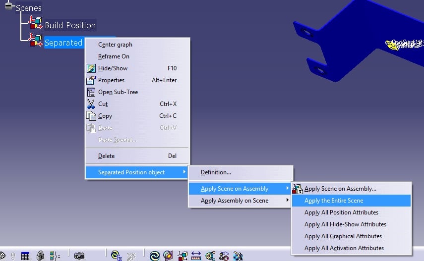
Once the user has multiple Scenes, they can switch between the two. If 3DCS features already exist in the model, select Update Model and the points, features, and mesh will move to the new location of the parts.
To swap between Scenes, right-click on a Scene in the CATIA tree; highlight the Scene Object; highlight Apply Scene on Assembly and select Apply the Entire Scene.
What about making a Scene in 3DCS?
With 3DCS and Enhanced Scene, the possibilities are basically endless. Here are a list of suggestions other modelers have used with 3DCS:
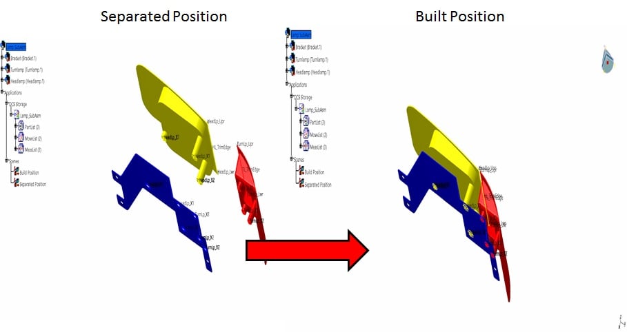
- Creating a Design Position scene and a Translated Position scene, the user can then switch back and forth to check for errors and to verify that the design was met.
- Try applying a move to your 3DCS model. When the parts are in the new position, save it as a Scene. Now, switching back to the design position Scene will all you to see if there are any issues with your 3DCS model or the design.
- If there are several parts in the assembly and you only need to work with a few of the parts, you can use a Scene to set your viewing parameters. Simply create a Scene specifying which parts to hide, show, change color, change edge thickness and so on. Now you can use the Scene to quickly isolate the parts you want to work with.
- Save a specific sample from the model’s simulation. Start by using Show Samples, and selecting one of the samples. Then, set the part position and save as a Scene.

Find more Tips and Tactics at DCS’s blog at http://blog.3dcs.com.
Sign up for DCS's newsletter (http://www.3dcs.com/mailing-list.html) to get each month's Tips and Tactics and DE Focus right to your mailbox.
Questions? Call or email DCS, and we’d be happy to help.
DCS Dimensional Control Systems
580 Kirts Blvd ste 309
Troy, MI, 48084
(248) 269-9777


No Comments Yet
Let us know what you think