DCS begins its Digital GD&T Series with a trio of webinars showing how to create GD&T in your CAD platform
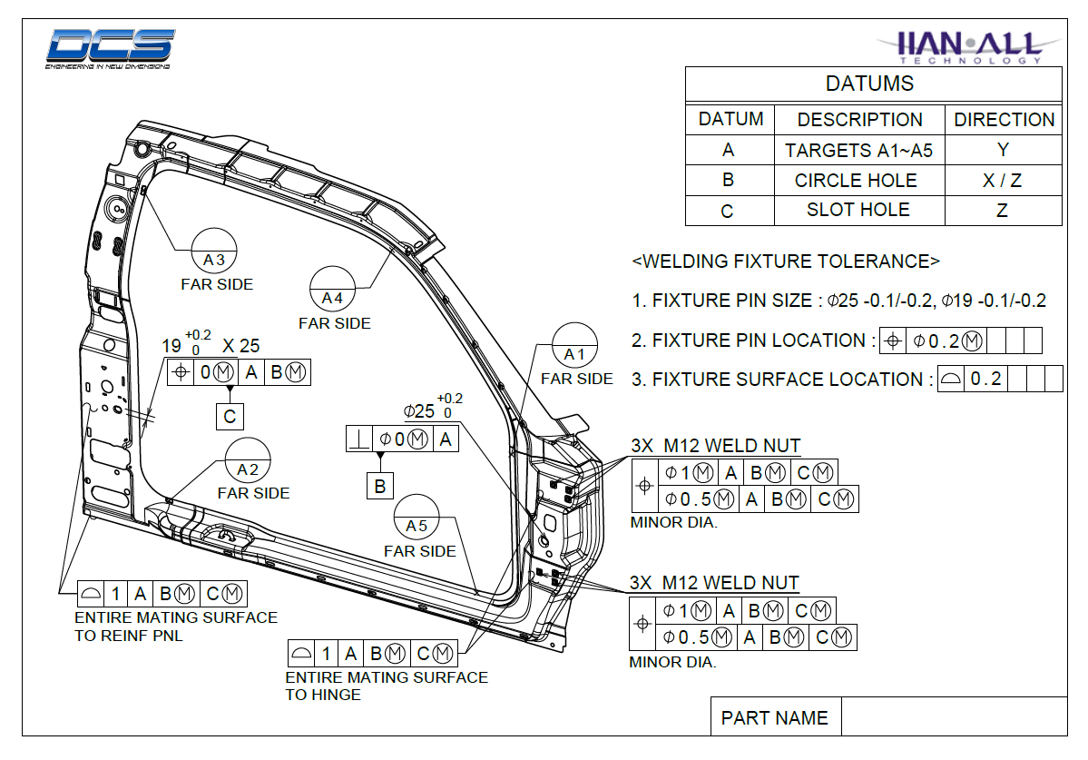
To begin MBD with 3DCS, a modeler starts with the CAD model itself. The GD&T placed on the CAD becomes the source of the 3DCS Monte Carlo Simulation, along with assembly process and simulated measurements. In order to promote the use of the CAD model as the single source of information, the designers need to create the GD&T in the CAD system. This Embedded GD&T is then leveraged throughout the entire product lifecycle for creating measurement plans, describing to manufacturing their tolerance objectives and assembly processes, and as a tool for root cause analysis and problem solving.
3DCS gives users the ability to create tolerances in a variety of ways. Modelers can add GD&T in 3DCS (instead of the CAD platform) and can also add point or feature based tolerances. These inputs can be used as inputs for the Monte Carlo Simulation and Tolerance Analysis. However, the process works best when the GD&T is defined in the CAD Platform as Embedded GD&T, called Functional Tolerance Annotations (FTA) in CATIA and Product Manufacturing Information (PMI) in NX and CREO.
Embedded GD&T has a variety of benefits to the 3DCS and QDM user.
Click to View the Whitepaper on the Value of Embedded GD&T
When FTA and PMI are defined in the model, this information is then brought into 3DCS with the push of a button. This keeps users from having to recreate the GD&T in 3DCS, thus removing the need to remake already created information which both wastes time and creates additional opportunities for error.
When utilizing Embedded GD&T in the form of FTA and PMI, 3DCS Software has the ability to not only read that data in, but also to push new values back to the CAD model. This gives 3DCS users the ability to validate and test the GD&T, and then update the model's GD&T. Otherwise, that information needs to be output from 3DCS either manually or as a report and re-authored in the CAD model.
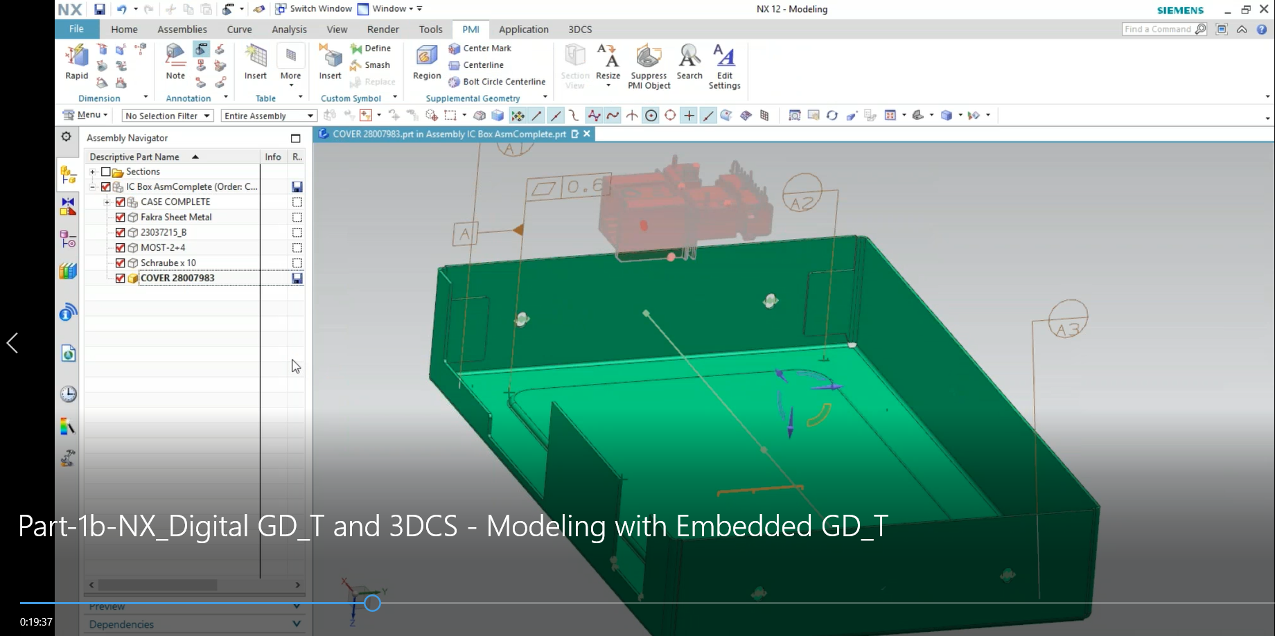
When GD&T is defined in the CAD model, using it in your 3DCS Model is both fast and easy. By selecting Update GD&T in the Update Model menu, 3DCS reads in all the Embedded GD&T on a selected part or assembly. This is a great deal faster than creating the tolerances manually, as any automated process is faster and easier than a manual one, and guarantees that the correct GD&T is being applies.
With Joints and Constraints defined in the CAD as well, 3DCS modeling becomes very easy. Joints and Constraints can be read in as 3DCS Moves, essentially, when combined with Embedded GD&T, creating the entire 3DCS model with only a few button clicks. The user only has to add a few measurements for outputs and then run the analysis.
Watch the recorded session of Part 1 of the Digital GD&T Series - Demonstrating how to create Embedded GD&T in your CAD platform. Contact DCS if you would like the model from the event.
Creating FTA in CATIA V5 | Creating PMI in NX | Creating PMI in CREO


North American Innovation Center
28064 Center Oaks Ct A, Wixom, MI 48393
Call us: +1 (248) 504 6200


No Comments Yet
Let us know what you think