The Add-on module 3DCS Inspection Planner gives engineers the ability to quickly generate inspection and measurement plans from CATIA and 3DCS points. Built on the QDM ANALYST engine, the integrated tool takes points from CAD, and creates report templates for measurement data, as well as full inspection plans to be used on the shop floor.
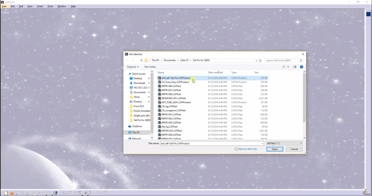
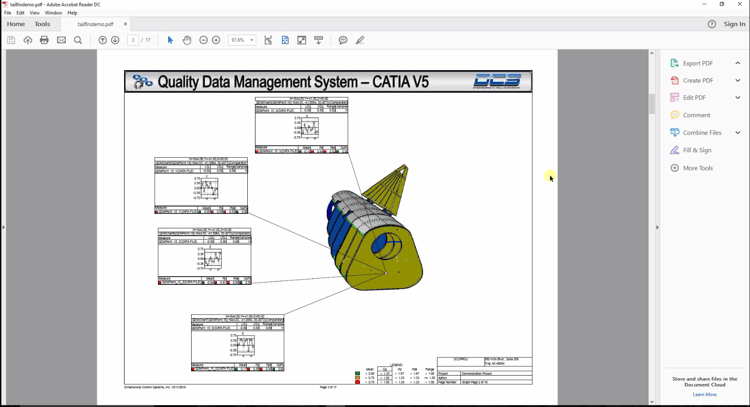
As mentioned, the whole process begins with a model in CATIA. In this case, we're using CATIA V5 as an example. Open your model in CATIA.
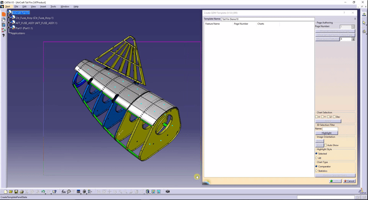
Select the points on the CAD model that you want to track through the manufacturing process.
How do you determine which points to focus on?
There are a couple of methods:
1. Historical Information - based on previous production runs, which areas have caused build concerns and need to be monitored.
2. User Experience - many engineers have experience working on the shop floor and with manufacturing processes. With common processes, there are often areas of concern that regularly cause issues and need to be monitored.
3. Monte Carlo Simulation - based on the analysis results, key contributors to variation can be identified, and those points used to monitor them throughout the manufacturing process.
4. Issues on the Shop Floor - when using Model Based Definition to resolve plant floor issues by utilizing plant data with CAD, new points can be identified and the measurement plan can be updated to include them.
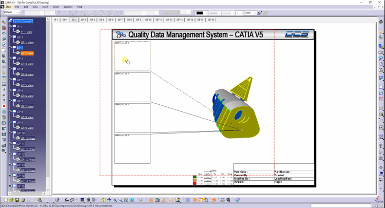
Once the points are selected, Inspection Planner opens draft mode to adjust the parameters. The user can move the chart templates and change the metrics, charts and format of the template.
Once complete, the measurement plan template is saved to the local network. Alternatively, the template can be saved to a web based quality system, or sent to a supplier or plant for use on their local network.
The template uses a QDM ANALYST framework, and is saved with the company, plant, product and other information to identify the parts being inspected.
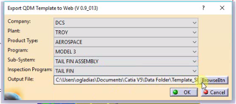
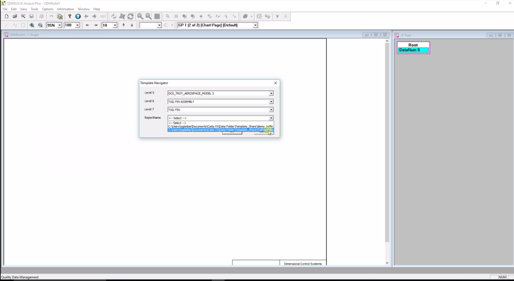
From the shop floor, the template can be accessed by the same kind of drop down selection that was used to save it. This makes it easy for inspection labs and plant managers to select the templates they need based on the parts they are inspecting, rather than selecting files from the network, and worrying about which template, which file or which iteration to use.
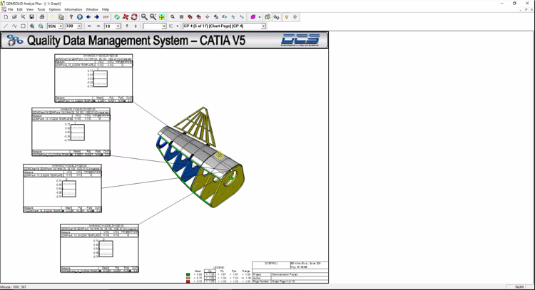
After opening the template, last minute adjustments can be made. Charts can be moved, changed or removed. Are you interested in just one particular hole or point? Is there a surface profile that needs to be addressed? Quickly adjust the template to showcase the information you need to see or share.
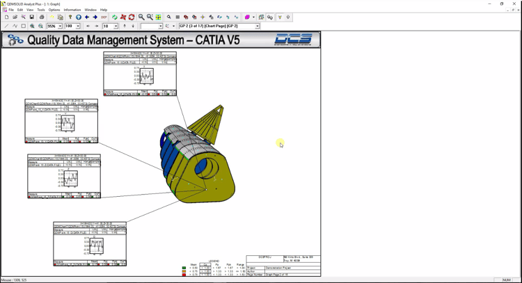
By accessing a web based system, or by selecting data sets from a measurement device, the template is updated with information. This populates the charts and metrics automatically.
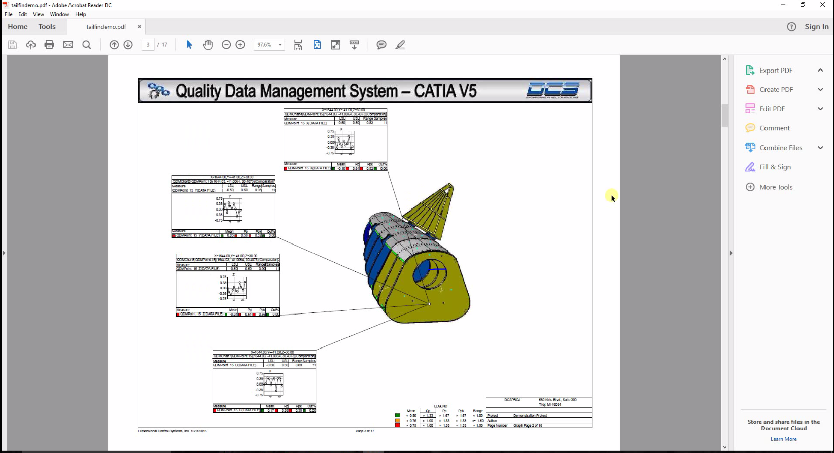
Once populated, the information can be exported as a pdf, excel sheet or in specific formats for downstream applications and PLM systems.
This allows instant access to the results of measurement data from any source, or multiple sources for comparison, and based on the points critical to the build. From here, the user can collaborate with key decision makers or share the information with their team.
If an issue is found, the data can also be pushed back into the CAD model for analysis and resolution by correlating the measured points with the CAD points. Run Monte Carlo simulations using plant data and find the source of your build problem, and then update the measurement plan to monitor the new solution for success.


North American Innovation Center
28064 Center Oaks Ct A, Wixom, MI 48393
Call us: +1 (248) 504 6200


No Comments Yet
Let us know what you think