Use GD&T to Put Tolerances on Your Model
3DCS Now Has a Complete GD&T Interface for Building PMI onto Your Simulation Model
3DCS Version 7.6 is now available to all DCS Clients with active maintenance -- go to https://fileshare.3dcs.com/ to download the new version.
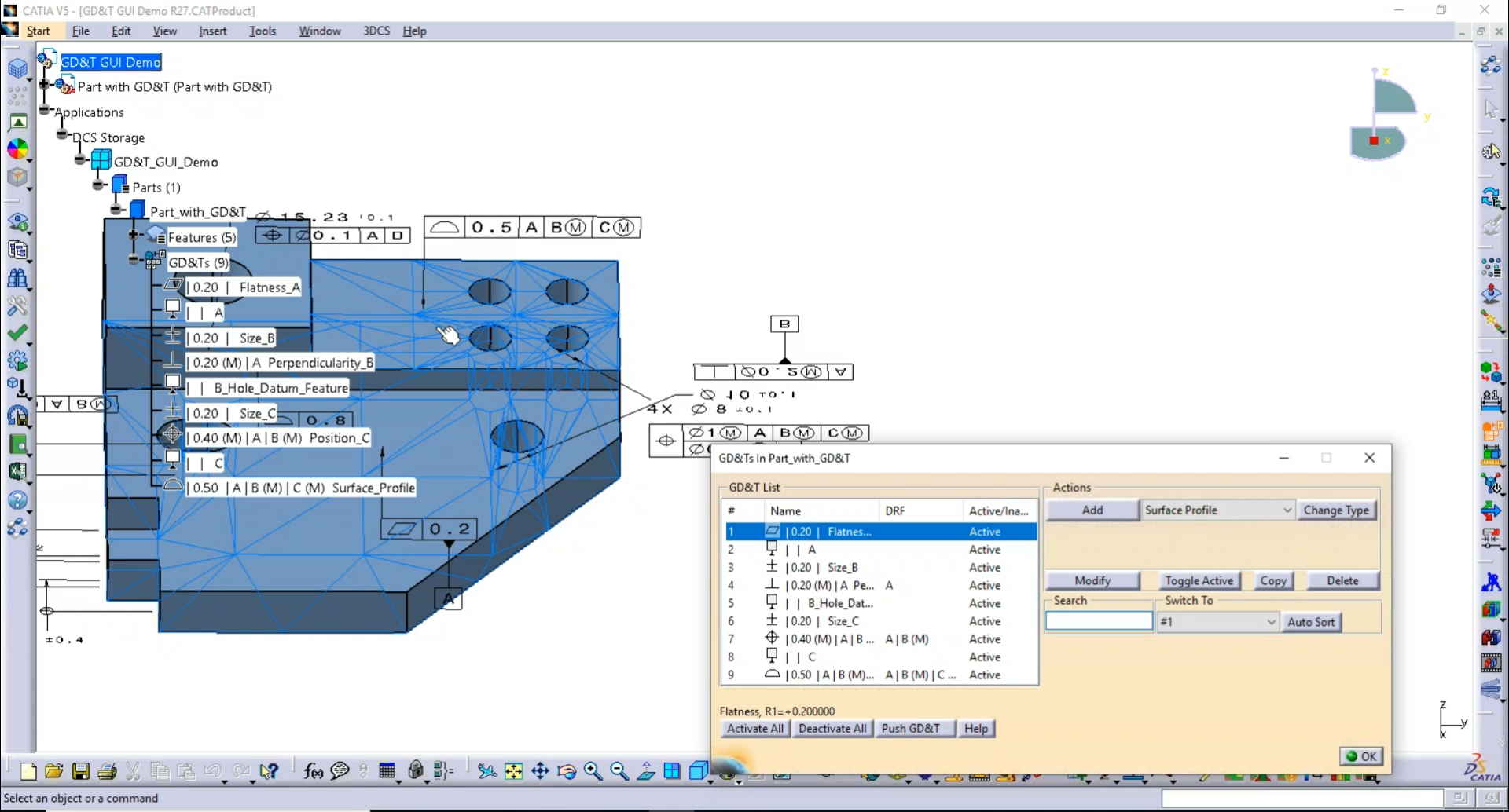
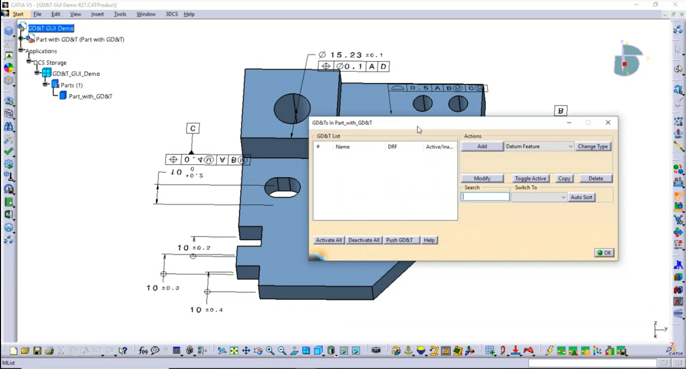
3DCS Version 7.6 introduces a new GD&T interface that provides the tools to apply GD&T to your model. The GD&T is then used as the tolerance inputs for your Monte Carlo analysis. This provides a number of powerful benefits:
1. Optimize CAD PMI and GD&T -- Push back optimized GD&T to your CAD model
2. Simplify the tolerance process -- Utilize the standard language of GD&T to plainly add tolerances onto your model.
3. Create more granular analyses -- With each tolerance (even angularity) having it's own callout or part of a particular call out, it is easier to determine the specific input most responsible for
The new interface, available in all versions of 3DCS (NX, CATIA, CREO, MC, 3DEXPERIENCE)
Introduction to the NEW GD&T Interface
Questions About the New Version of 3DCS
If the CAD size is not the size intended can you change the size value here?
The GD&T interface does not have any impact on the nominal of the Features of Size (Holes, Pins,...) The CAD must be modified to change the nominal or Coordinate "DCS" Points can be used. You may be able to, as a quick work around, adjust the size in 3DCS software by changing the offset of the size
Is this 3DCS update available for NX, Creo or Multi-CAD?
Yes, absolutely. All versions of 3DCS (NX, CREO, CATIA, Multi-CAD, 3DX) have the new GD&T GUI.
How do you set the GD&T Standard, say ISO?
We have a setting in the DCS Preferences to select ISO or ASME.
Will you be adding GD&T views to the automated reporting functionality in the future?
The GD&T view sis already in version 7.6.
When you state that the Feature Tolerances will be removed, that excludes legacy tolerances such as linear, circular, etc? In other words, those legacy tolerances will stay for the foreseeable future?
Yes, they are needed as pre-requisites for other functions in the software.
How does 3DCS recognize whether the datum B should be defined on the axis or on the cylinder surface?
It is feature based, so datum B is the axis created by the feature.
Will it warn us for improper GD&T? e.g. over-constrained?
We have a preliminary GD&T checker in the Joint wizard. Mike will show you momentarily.
Do we need CATIA FTA license to push GD&T back into the CATIA model?
No, but you do need it to create new FTA in CATIA.
How does the analysis of a feature tolerance without a DRF compare to the new GD&T tolerance with a DRF?
The GD&T Profile can be defined From Nominal or No DRF; this eliminates the need to use the Feature Tolerance with Grouped or Independent.
Do the GD&T panels work with coordinate points?
Yes.
When the Tolerance Wizard is improved for GD&T, can you please give it a single Icon in any of the other toolbars. The wizard as a dll function is really good, and which I really often use. It is so useful I do not understand why there isn't an extra icon to start it directly...
Yes. This is our plan. It will be in the standard taskbars and ribbons soon.
View the First Part Now On-Demand by Clicking Below


No Comments Yet
Let us know what you think