DCS Workshops Teach Tolerance Analysis Skills - FEA and Modeling Tips
DCS Workshops at the DCS Global Technology Conference teach new users how to bring Finite Element Analysis into their tolerance analysis simulations and a series of tips, tools and tactics to improve modeling speed and efficiency.
From Tackling Tough Tolerance Analysis Scenarios - DCS Conference Day 3
DCS Workshops - Modeling Efficiencies and FEA Compliant Modeler
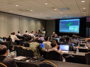
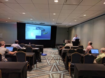
With the morning over, the room was re-formed into two smaller rooms to conduct the training workshops. There were two workshops in total, and all attendees were able to attend one, then the other.
FEA Compliant Modeler -
Finite Element Analysis + Tolerance Analysis
Click to View the FEA Compliant Modeler Workshop Video
The FEA Compliant Modeler workshop used 3DCS FEA Compliant Modeler, the add-on module that brings finite element analysis (FEA) into your tolerance analysis to account for flexible and compliant parts. The workshop was aimed at new users, and designed to teach the skills to help 3DCS users expand their ability to include this kind of advanced analysis.
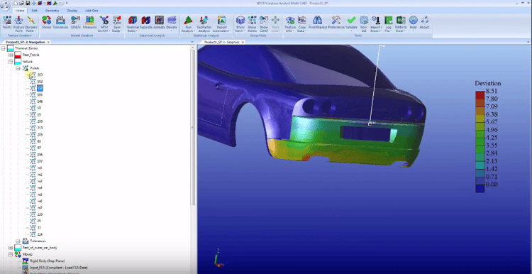
As an introduction to FEA Compliant Modeler, the workshop began with a walk through of a completed model to show the difference between a rigid body model and a compliant model.
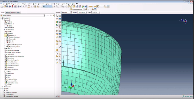
From here, the mesh files and use of an FEA solver was shown. 3DCS uses a mesh file from a CAE solver like Abaqus to map the material properties onto the CAD parts, linking the mesh nodes to 3DCS nodes on the part itself. This lets the software act on the individual nodes in order to deform the geometry.
After the initial demonstrations, Saurav Kakar, DCS FEA Specialist, showcase the different tools in 3DCS FEA Compliant Modeler that can be used in your models.
Agenda:
- Specific Questions Q&A
- Completed Model Demonstration - Compliant Moves and Components (Rear Fascia)
- Open mesh file in Abaqus CAE
- Walk through of the mesh file in Abaqus
- Export Mesh file
- Open Mesh File in notepad
- Discussion about nodes and material property units
- Apply Stiffgen to the model
- Input FEA data to the move
- Demonstrate the Point linking wizard.
- Discussion about test moves in the model and how to test if the mesh file is working as desired
- Gravity move (Summary to show value of gravitational force used in software)
- Thermal move (Thermal file is created for 1 degree Celsius change of temperature and then multiplied by change in temperature input in the move)
- T Matrix
- Color Mapping
Modeling Efficiencies - Model Faster and Easier
This workshop went through a variety of tolerance analysis tools, tips and strategies that can be used to make modeling faster, more efficient, and make updating the model later on a lot easier.
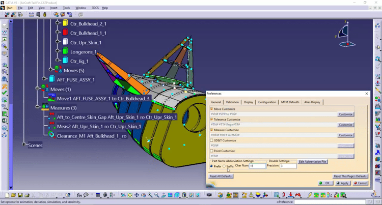
Beginning with setting up your model, there are a number of things you can do as a modeler early in the build process to make your overall modeling easier.
Setup
- Tree structure
- Scenes/Arrangements/Exploded Views
- Alias Display
- MTM Defaults
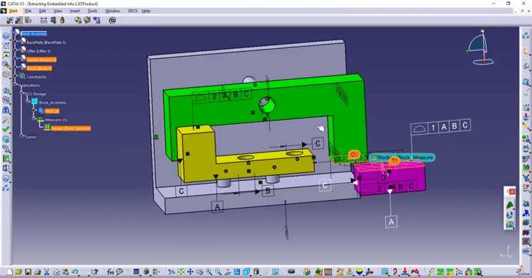
During the creation of Moves, Tolerances and Measures (MTM), as well as creating points, there are both tips and specific tools within 3DCS that speed things up and simplify later changes.
Point and MTM Creation
- Fast point
- Right-click Menu
- Copying Data
- Cloning
- Process Capability Database
- Extracting embedded CAD information
- Mirror/Duplicate
- Measure Generator
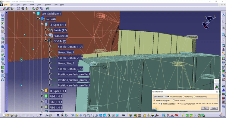
After your model is complete, it is important to double check your work. When running simulations, there are some tips that can get your results quickly, especially if you are running iterative design optimization. Finally, you'll want to modify your model, and quickly, and there are tools in place that can make this fast and easy.
Validation, Modifications, and Simulation
- Tolerance Wizard
- MTM Info
- Find/Replace
- Excel Export and Import
- Tips to reduce simulation run time
Click to View the Modeling Efficiencies Workshop Video
Need to Download the Videos?
Contact DCS Direct to get a download link.


No Comments Yet
Let us know what you think