 The Cross Sectioning tool can be used to visually improve a large model. Sometimes a visual check is all that is needed to verify a part is perfectly tangent to it’s mating part.
The user can also validate by using a screen-check measurements, create points and MTM’s (Moves, Tolerances, Measurements) in 3DCS Variation Analyst. CATIA users can use the Sectioning tool while 3DCS is in Animation Mode.
To gain access to the Sectioning tool, CATIA users will need to add the Sectioning tool into their 3DCS workbench.
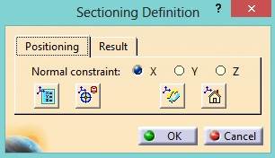
With a model open, start the Sectioning tool. The Sectioning Definition will appear.

In the Positioning tab, the user can specify the section plane direction in either X, Y, Z directions.

Note: If the user changes the assembly from Creation Mode to Animation Mode, the user will need to recreate the section.
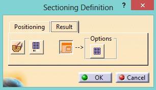
 In the Results tab, these options can be used to change how the section is viewed.

Note: If the assembly is in Nominal Build in 3DCS, it will still cut the geometry but no section will be displayed in the section/preview window.

In 3DCS Multi-CAD, the user can create a cross section from the Graphics toolbar.

Note: Once the user modifies the cross section (offset or rotate) it no longer becomes an X, Y, or Z cross section. Open the Custom Cross Section and select Close and Hide to remove the cross section.

Using this function can help remove some of the interlying visual blockers in a model, and thereby make it easier to inspect your work as you progress through the model. CATIA and 3DCS are filled with helpful 'quality of life' features such as this.
Download the article below to archive and share, and visit DCS's CATIA V5 Integrated Version of 3DCS to learn more!
These Stories on CATIA
No Comments Yet
Let us know what you think