<img alt="" src="https://secure.smart-enterprise-365.com/779147.png" style="display:none;">

Why Be Afraid of Profile GD&T - Advice from an ASME GD&T Trainer

Gili Omri
Jul 28, 2020 11:10:59 AM

Overcoming the Fear of GD&T on Drawings 

Does manufacturing see GD&T on their drawings and jump to conclusions? Do they try to replace it with basic dimensions? 

By DCS partner Gili Omri, TES Rnd and ASME Certified expert in GD&T

,Who is afraid of Profile GD&T? TES RnD
 

Who's Afraid of Profile (GD&T)?


At a recent visit in a machine workshop, one of the metrologists announced that “Engineering truly lost it…”. To prove his point, he showed a drawing similar to Figure 1

Understanding Profile Callout Example - TES RnD

Figure 1

He explained that Profile is hard to inspect (requires CMM), and it is not clear how it should be reported, the drawing would have been much simpler to inspect if instead of the Profile there was a Plus/Minus location dimension (as depicted in Figure 2

Figure 2

Plus/Minus inspection he said is simple:

  • Place the workpiece on a measurement plate
  • Calibrate a height gage to 40 millimeters
  • Sample a sufficient number of points on the surface
  • Report Min and Max Values found

Recording the measurement example - TES RnD

Is the meteorologist correct?

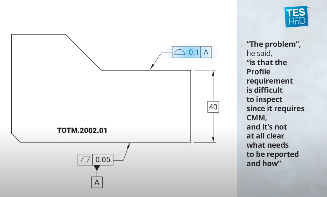
Is Profile a complicated requirement?

Let’s take a closer look, but standard wise:

Plus\Minus

ASME and ISO definitions of size are different:

As to ASME Y14.5-2009 1.3.54; Actual Local Size is the measured value of any individual distance at any cross section of a feature of size (as depicted in the figure).The proposed procedure does not account for the possible gap between the measurement plate and the base surface. Also the measurand is not the individual distance between point pairs.

As to ISO 14660-2:1999, 3.6; Local Size of two parallel extracted surfaces is the distance between two points on opposite extracted surfaces, where the connecting lines of sets of opposite points are perpendicular to the associated median plane (as depicted in the figure)

The proposed procedure does not account for the possible gap between the measurement plate and the base surface. And measurement direction is perpendicular to the base plate but not necessarily to the Median Plane.

So it appear It appears that the measurement procedure does not comply with ASME nor ISO, additional assumptions or measurements are required.

Profile

On the other hand, the proposed procedure agrees with the related Profile requirement. The surface must lie within a Tolerance Zone established by two planes equally disposed about the Nominal surface


Profile Definition - ASME - TES RnD


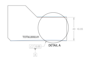
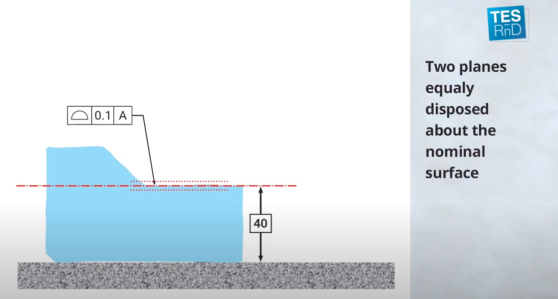
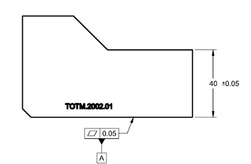
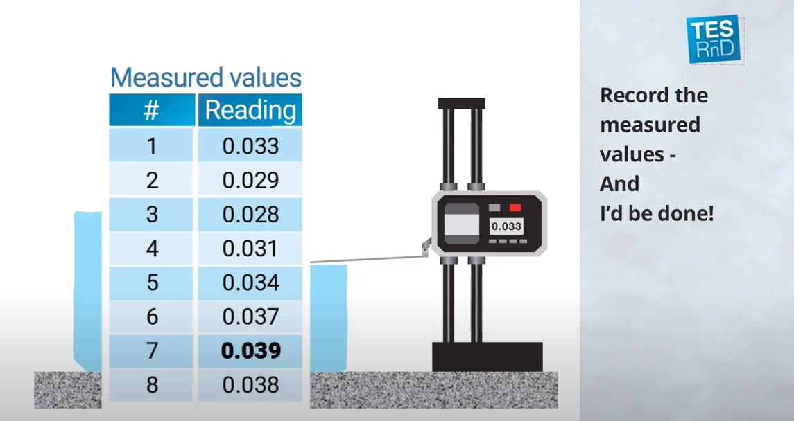
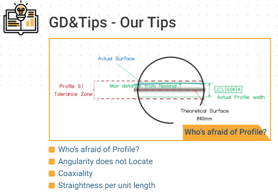
The Profile value, to be reported is the width of the actual tolerance zone, e.g. the maximum distance from the Nominal location Relative to the Measurement Plate X 2.


CloserThe measurement solution is the same - TES RnD

So, to sum it up, the meteorologist was badly informed, in this case Profile measurement is what he had in mind.

  • In this case Profile is NOT hard to inspect (Does NOT requires CMM),
  • Reported values are well defined.


Bottom Line

Even if we did something “a thousand times ”and “everyone” understands what it means,

it may be common and accepted,

But still nothing more them “Tribal Knowledge”

Geometric Tolerances are a tool to define Geometric Functional Requirements

State Standard & Revision to assure proper Decoding

Write to get it Right


Watch the Video: 


Read more tips on GD&T at TES RnD

More tips from TES RnD

https://www.tes-rnd.com/en/gdtips-2/


About the Author

Gili Omri, Founder & CTO at TES-RnD.

GD&T - Get it Right the first time - TES RnD

https://www.linkedin.com/in/giliomri/

Expert in GD&T, holder of ASME (American Society of Mechanical Engineering) certification at its highest level, Senior GDTP -S.

Delegate of Israel in the ISO committee that deals with the GPS standard (specifications and validation).

Technical expert in the ISO TC213/WG18 GD&T working group. Mechanical engineer with years of real-world Mechanical R&D experience.

I provide GD&T training and consulting to companies in wide array of fields such as Aerospace, Defense, Medical devises, Semiconductors, etc…
GD&T (ASME) and GPS (ISO) training and consulting focus on functional constraints and the interdependent relationship between design, production and quality. The training has proven its effectiveness and is delivered to small, medium, large international companies.

Promoting Variation Analysis software to mitigate non-compliance, assembly issues, and similar risks as well as product and process optimization upfront.
Expert in utilizing light-weight material (composite materials, magnesium) solutions, and design optimization.

Subscribe by Email

No Comments Yet

Let us know what you think