Edited 6-10-2015
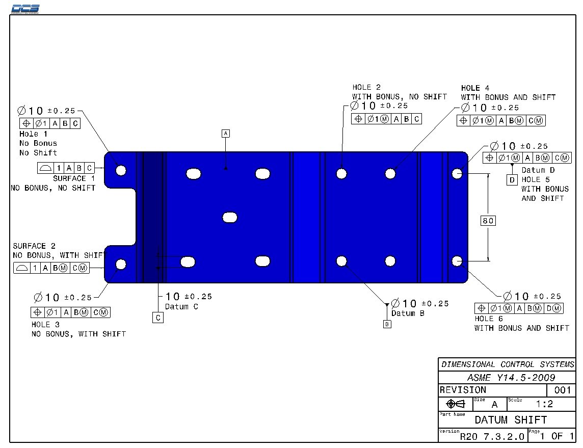
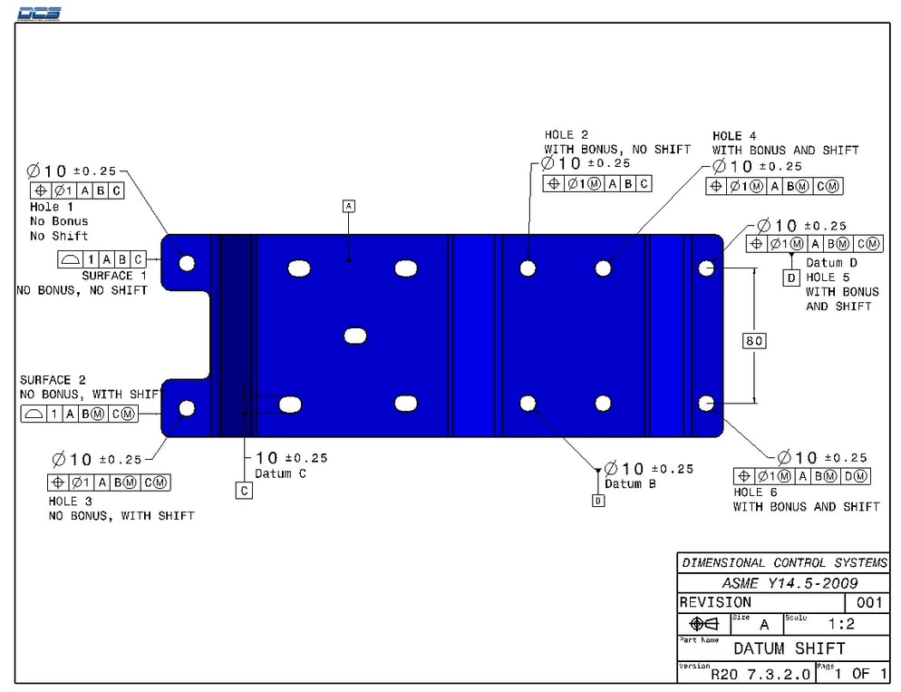
When a datum in a datum reference frame (DRF) is specified at MMC/MMB, the datum feature simulators (e.g. gage pins) will be made as though the datum features are at their MMB (e.g. holes at their smallest size.) Therefore, when a part with datum features not at MMB is placed on the gage, it can be adjusted so that the features being measured are closer to nominal. Since the measured variation is less, the features can have more variation relative to each datum axis or center-plane.
In 3DCS, Datum Shift is applied by activating the floats in the internal feature moves used to control the features in the callouts back to their respective DRFs.
To test Datum Shift in 3DCS, with the new example model (...\example_models\DatumShift), first turn on Datum Shift for the model.
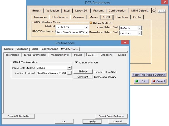
The option to add Datum Shift to a model is located in the 3DCS Preferences -> MTM Defaults tab -> GD&T tab. The Datum Shift option is on by default.
Then, simulate the Worst Case of the model using the dcu_simu_fn.dll. Launch the DLL and apply 1,000,000 to the total runs field and pres Start>>.
|
Holes |
Description |
GD&T Stack (Range) |
GD&T Stack and Geometric Affect |
|
1 |
No Bonus, No Shift |
1.0 |
1.0 |
|
2 |
With Bonus, No Shift |
1.5 |
1.5 |
|
3 |
No Bonus, With Shift |
1.5 |
1.94 |
|
4 |
With Bonus and Shift |
2.0 |
2.36 |
|
5 |
With Bonus and Shift (D) |
2.0 |
2.75 |
|
6 |
With Bonus and Shift |
2.0 |
3.0 |
|
Surfaces |
Description |
GD&T Stack (Range) |
GD&T Stack and Geometric Affect |
|
1 |
No Bonus, No Shift |
1.0 |
1.0 |
|
2 |
No Bonus, With Shift |
1.5 |
1.56 |
|
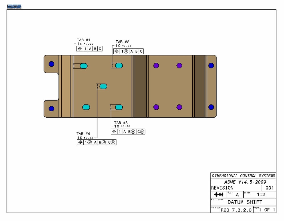
Slots |
Description |
GD&T Stack (Range) |
GD&T Stack and Geometric Affect |
|
1 |
No Bonus, No Shift |
1.0 |
1.0 |
|
2 |
With Bonus, No Shift |
1.5 |
1.5 |
|
3 |
No Bonus, With Shift |
1.5 |
1.5 |
|
4 |
With Bonus and Shift |
2.0 |
2.0 |
|
Minimum Wall Thickness |
Description |
GD&T Stack: Minimum |
GD&T Stack and Geometric Affect |
|
Holes 5 and 6 |
With Bonus and Shift |
68.25mm |
67.65mm |
DCS added a series of measurements to the test model, to confirm all tolerances and datum shift numbers affect the measurements correctly. Each available tolerance has a corresponding measure with direction specified at Y, Z and hole diameter size.
After installing Version 7.3.2.0, the example model used in this article will be saved into the following directories for you to test with (these are default directories):
Windows 7 & 8: C:\Users\Public\Documents\DCS\3DCS_MC_7_3_2_0_win64
Windows 7 & 8: C:\Users\Public\Documents\DCS\3DCS_V5_7_3_2_0_win64
Windows 7 & 8: C:\Users\Public\Documents\DCS\3DCS_V6_7_3_2_0_win64
The model will be named Datum Shift, and can be used immediately (the measurement data has already been created) by replacing the parts in the assembly.
If you have any questions, please post them in the DCS Community so we can share the answers and information with other users.
http://community.3dcs.com/3DCS

Sign up for DCS's newsletter (http://www.3dcs.com/mailing-list.html) to get each month's Tips and Tactics and DE Focus right to your mailbox.
Questions? Call or email DCS, and we’d be happy to help.
DCS Dimensional Control Systems
580 Kirts Blvd ste 309
Troy, MI, 48084
(248) 269-9777


North American Innovation Center
28064 Center Oaks Ct A, Wixom, MI 48393
Call us: +1 (248) 504 6200


No Comments Yet
Let us know what you think