
Click Here to Learn More about 3DCS Variation Analyst
The Six-Plane Move operation is likely the most commonly used move in 3DCS, but what happens when you have not three but four features that define a primary plane that you need to account for? That’s where the Auto Bend Move comes into play.
The Six-Plane move is the most versatile and general move in 3DCS. Most other moves can be done with the Six-Plane move if necessary. There are no orientation requirements for the six planes except that they must constrain all degrees of freedom.
The Six-Plane move does not require that the six planes be clearly defined as primary, secondary, and tertiary planes as does the Step-Plane move. An example of this scenario is when a keyed shaft is located in a V-Block fixture (shown below). The Six-Plane move is a good choice for locating parts that do not have purely perpendicular primary secondary and tertiary planes.
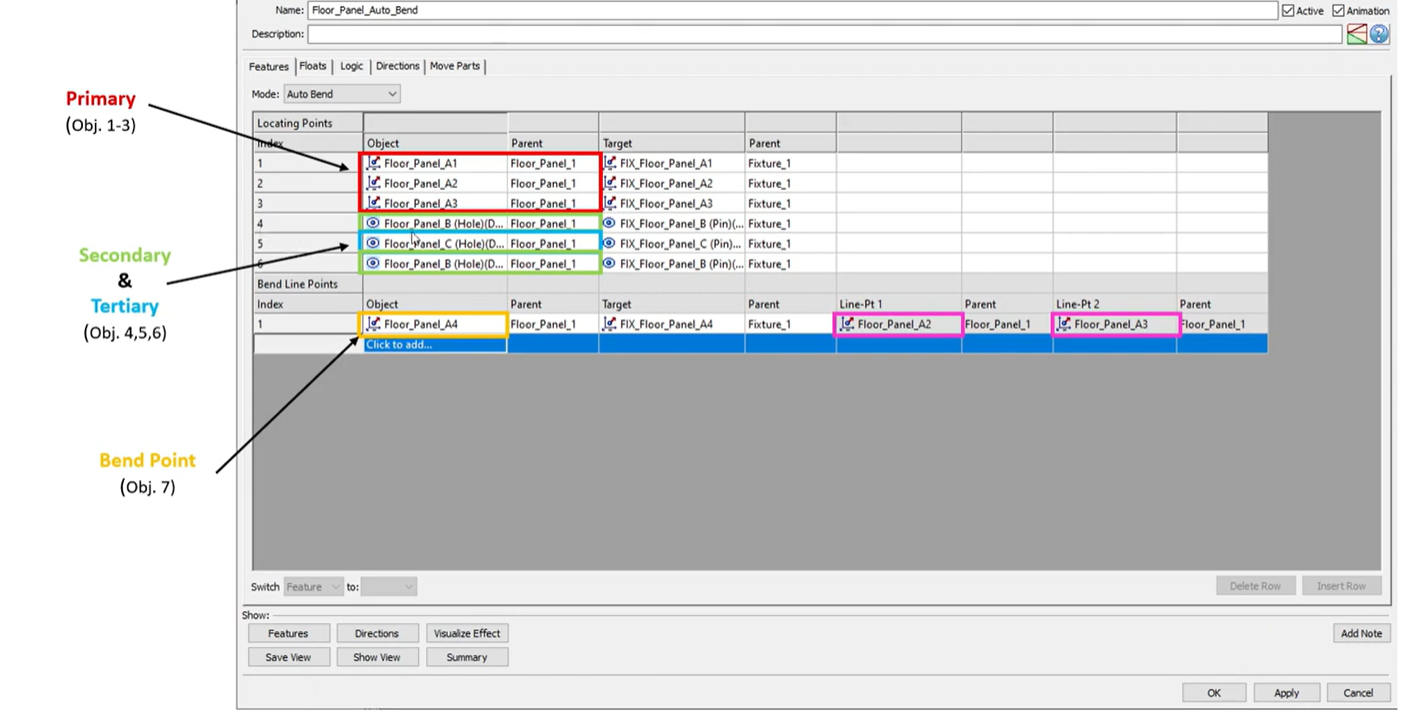
The Auto Bend Move operation allows the user to define a traditional primary plane using three features. It will then auto-calculate a bend line based on where the fourth primary plane point is located. The Auto Bend Move is not limited to only four primary plane points but selection order does matter as more points are added as the auto-calculated bend line is based on where the locations of the previous points. When substantially more than four primary plane points are used, there are likely better options than the Auto Bend Move such as the Best-Fit Move or the Segment Bend Move.
The Autobend move that handles components and assemblies that are over-constrained on the primary plane. These routines provide several ways to handle over-constraints using some automated rigid-body methods.
Beginning with the 3DCS v8.0 release, the Auto Bend Move has been given its own GUI and can be added directly through the Analyst Moves dropdown in the Moves dialog. Prior to the 3DCS v8.0 release, the Auto Bend Move was a part of the dcu_autobend.dll library and could be accessed through the User DLL Move dialog.
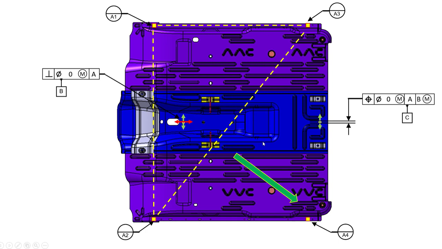
In this example, we use a floor pan from a vehicle to demonstrate how and when to use the Auto Bend Move. The Floor Pan has four “Datum A” targets that are used to locate the assembly to a fixture. By using the Auto Bend Move operation we are able to select the first three “Datum A” targets and then bend to the forth. By doing this we will accurately replicate how the assembly would be constrained to its fixture in the real world.
This video will lay out the scenario in which using an Auto Bend Move is necessary and walk the user through how to create an Auto Bend Move, step-by-step. By the end of the video the user will have a good understanding of the Auto Bend Move and have one more option in their toolkit to use in their models.


North American Innovation Center
28064 Center Oaks Ct A, Wixom, MI 48393
Call us: +1 (248) 504 6200


No Comments Yet
Let us know what you think