3DCS for Creo - Using Embedded Geometric Dimensioning & Tolerancing PMI to Create 3D Stack Ups
Written by Priya Vijayakumar, DCS Variation Analyst - Creo Specialist
The integrated version of 3DCS in Creo can utilize any embedded GD&T (PMI) to quickly create tolerance analysis studies and give you the information you need to make quality decisions.
As an integrated tolerance analysis software, 3DCS utilizes Creo PMI to validate design objectives and simulate potential build issues. To use PMI in your tolerance analysis software, you first have to create it in Creo. For this tutorial, the terms GD&T and PMI are used interchangeably.
Note: You can create and run stack-ups in 3DCS software without PMI. Using embedded GD&T and PMI streamlines your process and reduces the time it takes to set up your 3D tolerance stack ups.

Creating GD&T in Creo:
To start creating PMI in Creo, begin by setting the annotation orientation. Then add your GD&T callouts using the Annotation Feature.
- Define the active Annotation Orientation before creating the first Annotation in any session by selecting an Annotation Orientation from the Annotation Planes gallery .
- To create GD&T in Creo use the Annotation Feature function under the Annotation Toolbar, where the user can add multiple GD&T callouts and group them.

The following types of annotations are included in the Annotation Feature function:
- Driven Dimension
- Reference Dimension
- Ordinate Baseline Dimension
- Ordinate Driven Dimension
- Ordinate Reference Dimension
- Geometric Tolerance
- Set Datum Tag
- Surface Finish
- Specify Sheet Metal from Model Properties
- Manufacturing Template
- Note
- Symbol
- Empty Annotation Element
- Existing Annotation

- Selecting each type will open a separate dialog to define the selected Annotation type.
- 3DCS can extract any annotation created using Driven Dimension, Set Datum Tag, and Geometric Tolerance, which will be discussed in this document.
Creating a Driven Dimension
What is a Driven Dimension?
- A driving dimension will change the geometry of the model
- A driven dimension will only measure an existing model without affecting it
Selecting Driven Dimension from Annotation Feature will open a Select Reference dialog where the user can define the dimension. When extracting GD&T from CREO, the surfaces picked as references will be extracted as Features along with the dimension into 3DCS.

- Completed GD&T callouts are listed in the Annotation Feature dialog.
- The references selected for the dimension will also show up under the Reference column.
- Additional references can also be added using the Details... option in the Surfaces section.

- After selecting the References and creating a dimension, the user can now define the dimension in the Dimension Properties dialog.
- To get to the Dimension Properties dialog, select the Dimension in the Annotation Feature dialog and click Properties.
- The user can edit the name, tolerance, display, position and references of the Dimension in the Dimension Properties dialog.
- Only Dimensions created with tolerances get extracted into 3DCS.


Set Datum Tags in Creo
- Select the Datum Tag symbol from the Annotation Feature dialog to open the Set Datum Tag dialog.
- Enter the Datum name into the Name field.
- Under Reference select either Datum or Geometry and pick a Datum or geometric feature from the Creo Graphics Window or Navigation Tree.
- If the Datum selected has a reference surface, 3DCS automatically extracts that surface as a Feature for that Datum.
- Even if the Datum selected does not have any reference surfaces, the user can still add reference surfaces from the Annotation Feature dialog.
- The Placement option will allow the user to place the Datum Tags on either the Datum, Dimension, Geometric Tolerance, or Geometry.
- The Created Datum Tag will get listed in the Annotation Feature dialog.

Creating a Geometric Tolerance
- To add a GD&T callout, select Geometric Tolerance (GTOL) from the Annotation Feature dialog to open the Geometric Tolerance dialog.
- From the Model refs tab select the type of GD&T, Reference, and Placement.


After setting the Model refs, set the Datum refs and Tol value tabs to complete defining the GD&T


How to Extract Creo PMI & GD&T into 3DCS
See how easy it is to apply PMI to your model in the example video below:
How Do You Fully Leverage Your Creo CAD PMI?
Here is a walkthrough on utilizing Creo PMI with 3DCS tolerance analysis software:
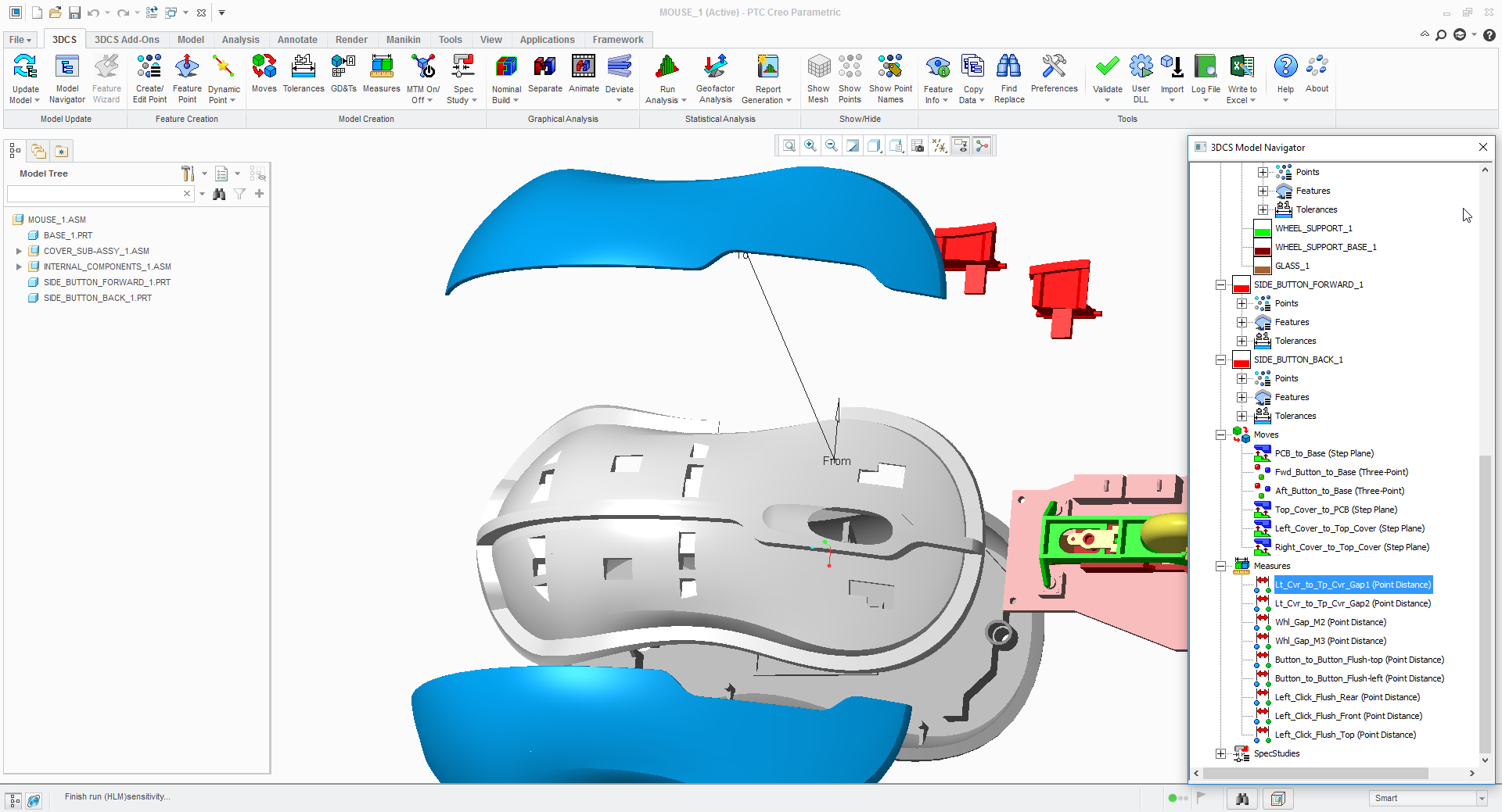
- Within Creo, switch to the 3DCS work bench and hit Update Model. This loads the model into 3DCS and to see the 3DCS Navigation Tree.
- Under the Update Model drop down menu, select Update GD&T.

This will open an Update GD&T selection dialog prompting the user to select the component to extract the GD&T from. The user can either select an individual component or the root to extract the GD&T from all parts in the model.
- Selection can be done either from Creo Navigation Tree or 3DCS Navigation Tree and the Creo Graphics Window.
- The extracted GD&T will be displayed in the 3DCS Navigation Tree within each part.

- The name entered in Creo is extracted with the GD&T and is the displayed name in 3DCS.
- In 3DCS, the GD&T dialog for each part lists all extracted GD&T.
- Double-click GD&T under a part/subassembly in the 3DCS Navigation Tree or select GD&Ts from the Model Creation toolbar and select a part/subassembly to open the GD&T dialog for that part/subassembly.

- The Feature List in the GD&T dialog lists all Features in 3DCS for each GD&T.
- Gtol Options will open the GD&T Options dialog. The GD&T Options dialog displays the extracted tolerance value as well as other options. The user can adjust the values for each GD&T callout in this dialog.

- Select Pick Ref Datum from the GD&T dialog to open the Pick Datum Feature Reference dialog. The Pick Datum Feature Reference dialog displays the Datum Reference Frame extracted from Creo. The user can also change the DRF to any other Datums extracted from Creo for any GD&T callout.


Tips and Tricks when Working with Creo PMI
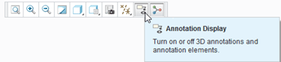
- If the GD&T created is not shown in the Graphics Window, make sure Annotation Display is turned on in the Quick Access toolbar.
- If the GD&T created in the Part level should be displayed in the assembly level Graphics Window, go to the Annotate tab, select Show Annotations, and select a part from the assembly in either the Creo Navigation Tree or Graphics Window. The Show Annotations dialog will list all GD&T created within the selected part from which the user can hide/show any GD&T.


- When the Datum Tag is attached to the GTOL frame, the Datum Tag follows the GTOL automatically when repositioned, preserving the attachment point on the GTOL frame.
- To edit the created GD&T in Creo the user should be in the Annotate workbench.
- To replace an annotation reference, right-click its name in the References collector, and click Replace on the shortcut menu, and select a new reference entity of a similar type.

- The Surfaces collector in the Annotation Feature dialog’s Surfaces section lets you select additional surfaces to be associated with the active GD&T. The Details... button below to the Surfaces collector opens the Surface Sets dialog box, which provides you with a variety of tools for defining surface sets.
Care to Share?
Download the pdf of this tutorial to archive and share with your colleagues


No Comments Yet
Let us know what you think