DCS has completed a number of projects for aerospace and defense companies, most of which cannot be disclosed. With the declassification of documents in recent years, some of these projects have been approved to be shown.
DCS is proud to showcase the work done to bring peace and stability to the galaxy.
The previously unmasked project can be found here - where DCS was instrumental in determining a solution to wing attachment positions on a defense aircraft for a major OEM.
As a precursor to discussing the Case Study Summary, it is important to note the processes that made the project successful. A disciplined engineering process with informational feedback loops not only organized and provided a clear vision for the project, but also allowed for continuous improvement once the OEM began production. Delivering the project's results, models and a quality system for real time SPC monitoring allowed for fast, corrective actions to be taken as part of a production problem solving strategy.

The program directives for the project were created and delivered by the OEM's management team, including engineering, production, staffing and executive. As a major vehicle production program, with estimated costs ranging in the billions of credits (conversion rate 1 credit (cc) = 2 US Dollars ($) as of 12-22-2017), it was key to align all the teams.
DCS was assigned the Functional Tolerance Analysis of the Drivetrain and Locomotion system, as it was a complex system that was required to meet multiple terrain requirements. With such an ambitious system set forth, and little historical data provided, DCS had a large task ahead.
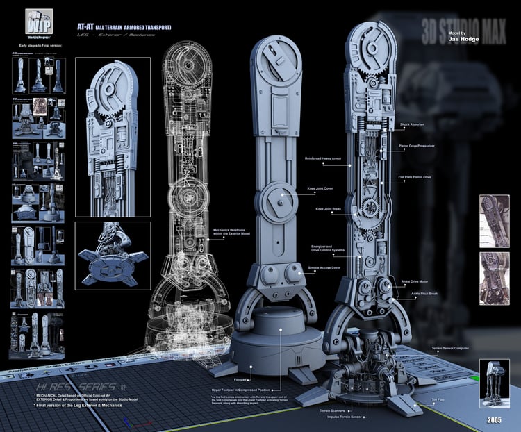
Most military style vehicles are less concerned with looks as they are with function, but determining gap and flush specifications is still key to designing a vehicle that can be assembled with little rework, and most importantly in this case, is resistant to wear and tear and can be repaired with modular components on the field. This meant that parts needed to fit the first time, and not have a chance to be built with such small gaps that there could be additional wear on components, or cause difficulty for teams in the field to do repairs.
Using Spec Study gave a rough idea of the appearance, to judge a starting point for these specifications, but as the primary concerns were based on assembly and not aesthetics, these were only a rough starting point. Analysis would be needed for any true specifications to be determined.
Determining Process Strategies was more difficult than anticipated. Due to the lack of historical and reference data provided, along with ambitious schedules and the complexity of the product, there was a large turnover of lead engineers on the DCS team.

To make matters worse, the design and engineering teams at the OEM had to get sign off for every email, drawing, CAD part, WTX file, phone call, or communication of any kind. A DNS was not sufficient, and security was extremely tight. The DCS team had to relocate off world to satisfy the needs of the security team, and DCS was sad to see few of them return...

What do you mean 'They have to sign off on everything'?!
This meant that oftentimes, the DCS team had to make design assumptions, and then go back and change the inputs when legal and security had finished signing off on design releases.
To keep the project moving, and to counter the two primary issues: that of a revolving (more like one-way) door of engineering leads, and the lack of timely information, DCS put two processes in place.
The first process was a decentralized system of responsibility and leadership. Two teams were setup in parallel, and worked together to complete the projects. In order to keep any information from being known by only one person at a time, and therefore risking the loss of the information should that engineer be found lacking in faith, the two teams were set side by side, and worked simultaneously on the same systems.
To improve efficiency, as having two teams doing the same thing is doubling your costs, and adding in the risk of additional human error and issues with version control, a CAD system that supported strong version control and promoted parallel work was needed.
DCS chose to use CATIA's 3DEXPERIENCE platform, which was being investigated by the OEM who still primarily used CATIA V5, to support the team's parallel work and version control. The unique setup of 3DEXPERIENCE, that of not having any file's but instead working with the raw data, allowed the engineers to keep control of versioning while also supporting multiple user modeling.
To speed up the analysis process, as each sub-assembly was completed, it was Black Boxed and put into a new 'Optimized Model' that would run much faster. This also helped with the collaborative efforts, as the results could be delivered from each sub-assembly as a single large component, reducing the amount of information that needed to be shared, communicated and logged.
As mentioned previously, information was not forthcoming in a timely manner from the OEM engineering and design teams, at no fault of their own. However, results were required by production and manufacturing teams. Failure to deliver was not an option, and an extension was vehemenantly denied, much to the chagrin of the engineer unfortunate to deliver the news (An intern was given the task). Therefore, in order to meet time constraints, assumptions had to be made.

So, that would be a 'no' on the extension, then?
Before adding the GD&T to the model, the DCS team took pains to make updating the tolerances easier in the future. Utilizing a Process Capability Database, the team connected all of the tolerances to an Excel database, allowing an update to the database to instantly update the model's tolerances. Then, when the design and engineering teams were able to deliver the GD&T, the DCS team could quickly change out the model's tolerances to validate the GD&T and propose any modifications to improve the design or reduce manufacturing costs.
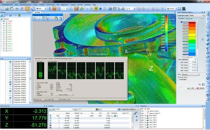
Using CATIA's GD&T Tolerance Advisor to create general tolerances and GD&T on the model, the team ran early Monte Carlo simulations to get an understanding of where in the design they would expect issues, and would need to tighten tolerances.
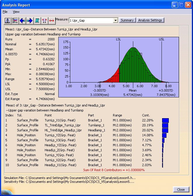
Example Analysis Output (Actual Project Outputs Cannot be Shared)
Using AAO - an add-on module that provides matrices and tables to view all of your models inputs at once, and analyzers to automatically optimize the GD&T based on the project specifications, the team had a working set of GD&T to move forward with.
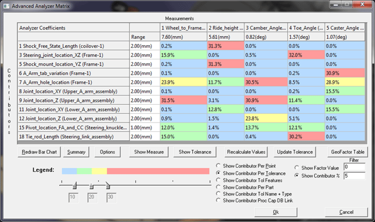
AAO indicates in a single table where the problems are - in this case, where to tighten tolerances
The Dimensional Variation Analysis is more in depth than tolerance analysis. Tolerance analysis usually encompasses a 3D tolerance stack, and a Worst Case analysis. Dimensional Variation Analysis begins with these and takes it farther by incorporating the assembly process as well as outside influencing factors.
Luckily, with the GD&T analysis results delivered, there was enough time to receive the assembly process from the OEM, giving the DCS team the information needed to accurately model the Moves. With the moves written, and the contributor list giving DCS an understanding of where to add Measures, combined with the Tolerances taken from CATIA's FTA GD&T, the model was complete and ready for analysis.
As the analysis was being run, the OEM's design team sent in an additional request. The vehicle needed to operate in environments ranging in temperature from -60 degrees Celsius, to 60 degrees Celsius. This could cause a lot of deformation on the parts, and they were concerned about mobility during the extremes.

Yup, I guess it gets cold there.
To help determine whether these temperature extremes would cause issues, DCS incorporated 3DCS FEA Compliant Modeler, which can be used to set temperatures and cause deformation of the parts at those temperatures before running new Monte Carlo simulations. This gave the team the ability to simulate the model at both extremes, as well as -40 degrees, -20, 0 degrees, 20 degrees and 40 degrees Celsius.
The design team wanted to know if this would affect functionality, though. This meant that static positions would not suffice. The locomotion needed to be simulated through its range of motion at different temperature extremes and with the GD&T variation (Worst Case as requested by the OEM) taken into account. If everything went wrong, and the vehicle were on an ice world, would it still be able to move?
To handle these requirements, DCS needed to add another module. This module, 3DCS Mechanical Modeler, allowed the model to be simulated through its functional range of motion. However, simulating the locomotion of the vehicle with Mechanical Modeler, 3DCS FEA Compliant Modeler deforming the parts for temperature extremes, and then running 10,000 Monte Carlo simulation to reach the level of accuracy the customer demanded meant that the DCS team would have to run seven very complex simulations, which would take weeks.
In order to get the results as soon as possible, as the customer was notorious for impatience,
We'll double our efforts!
DCS utilized the Cloud, offloading the analysis with Distributed Computing powered by Parallel Works. By adding a large number of machines, using 40 simultaneous computers for each analysis, DCS was able to get the results in 8 hours instead of 2 weeks per simulation study. In addition, by using the Cloud, DCS was able to run all 7 simulations simultaneously, getting all of the results in 8 hours instead of 3 and a half weeks. Needless to say, this gave all the engineers reason to sigh in relief.
To promote a Closed Loop Process of production problem solving (say that five times fast!), DCS created associated GD&T sheets and measurement plans from the completed CAD model. Using 3DCS Inspection Planner, integrated into the 3DEXPERIENCE, DCS was able to create CAD correlated measurement plans for manufacturing's CMM's and quality teams with a few button clicks. These were uploaded to the SPC Quality System that was being implemented for Quality Variation Control, which allowed the plant quality teams and manufacturing engineers easy access to the documents.
In order to continually monitor the suppliers and the primary assembly plant's quality levels, as delivering out of specification parts was absolutely unacceptible (and in many cases personally dangerous...), DCS implemented a Cloud Based SPC System to pull in the measurement data from all of the suppliers and the final assembly plant, and provide the customer's management team and engineers, as well as the on-site DCS team, real time quality metrics and the ability to pull reports of any quality issues that arose.
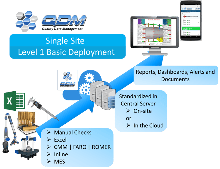
Essentially, how the QDM System functioned
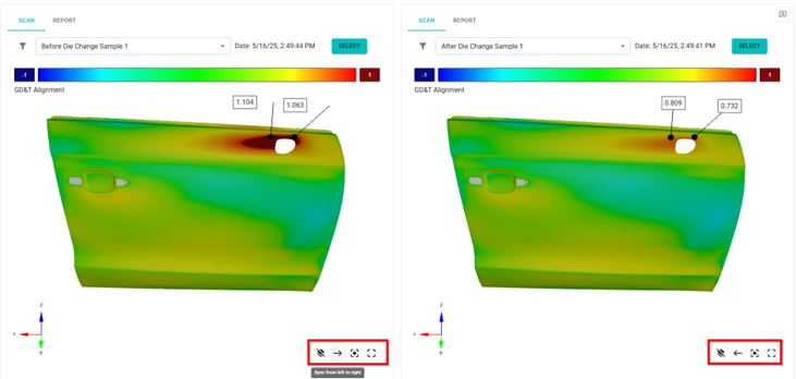
When a problem did arise, all of the teams were automatically alerted. A key component in the locomotion system was setting off the pre-set alerts. The component was not meeting quality specifications, and was causing issues at assembly. Pulling the reports, the DCS team instantly saw where the issue was, and requested a measurement data set from the system.
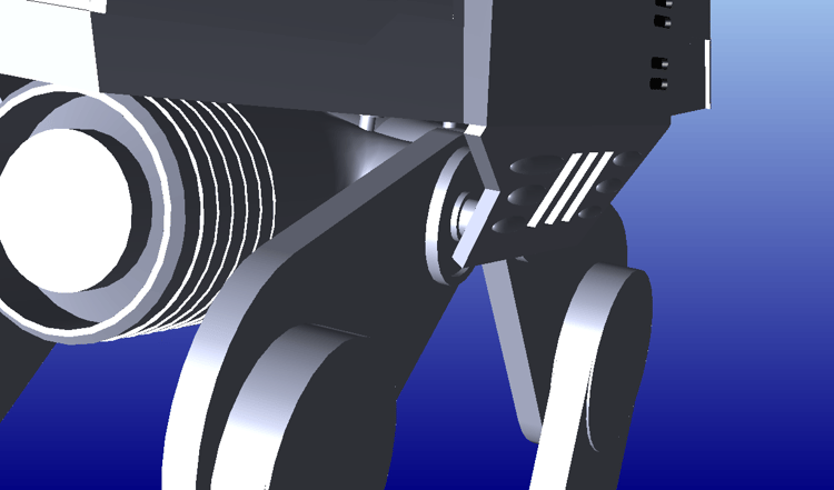
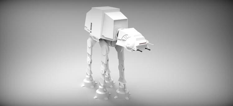
Something Was Wrong With the Actuator Do-Hicky - (Probably Because This Model Is Just a Big Block)
Taking the data set and replacing the CAD Model tolerances with the information from the supplier's CMM, the DCS team was able to recreate the problematic parts and situation virtually. Running new Monte Carlo simulations, and with the feedback from the supplier that the part was simply too large to meet the exacting tolerances set by the OEM, DCS was able to determine a new solution.
Design of Experiments, that is, creating a variety of solutions and then testing them all in simulation, allowed the DCS team to determine the optimal solution. In this case, a simple design change would allow the larger toleranced part enough clearance to keep it from negatively influencing the stack up. The design team made the adjustment to the armor plating that was too close to the leg, and the design was passed back down to production to make the adjustment. The change did not require retooling, only a slight modification to the locator strategy that affected final assembly of the armor plating that protected the upper leg mounts.
With this feedback loop of real time monitoring, automated alerts, information upflow to simulation and design, then downflow of validated changes, management could be content to know that any production problem would be identified, root-caused and resolved quickly.
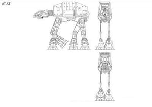
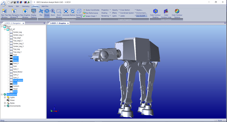
Objective 1: To determine the viability of the current design given enviromental and manufacturing variation of the AT-AT Walker before production.
Solution: DCS put a team on site that utilized a combined tool suite in conjunction with Distributed Computing in order to simulate the variation, and get results in time to meet ambitious deadlines. These results showed a number of issues in the assembly process that required design changes, which were then virtually tested to validate the solutions.
Objective 2: To put in place a system that would allow for real time monitoring and production problem solving once production began.
Solution: DCS incorporated a Cloud based SPC System, QDM Cloud, that could be used in parallel with the OEM's existing systems. QDM Cloud was tied to the suppliers and final assembly plant, with a process in place automating the collection of measurement data from their CMM's, the point cloud files and the Excel sheets with the hand measurements. These were centralized in the Cloud, and then mined by QDM to deliver automated alerts, dashboards with real time SPC metrics, and on demand reports for engineers and quality professionals to root cause and resolve production problems.
In additon to this, the system could be accessed by the DCS team to download measurement data that could be uploaded into the CAD model and used to find the source of production issues and test solutions through Design of Experiments (DOE) before updating the primary CAD design.


North American Innovation Center
28064 Center Oaks Ct A, Wixom, MI 48393
Call us: +1 (248) 504 6200


No Comments Yet
Let us know what you think