![]()
This article is from DCS's monthly article series the DE Focus included in each of DCS's monthly newsletter.
Datums are the origins for both Tolerances and Measurements. Figure 1 shows a datum example [ASME Y14.5-2009, 49]. Datums are established to ensure consistency between design intentions, manufacturing processes, and inspection plans.
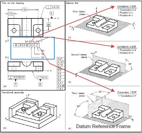
Figure 1. Datums constrain Degrees of Freedom of a part
To make a datum, a feature or a group of features is designated for the datum. The selected feature is called a Datum Feature.
Datum Feature Selection
(S1) A good datum feature is a ‘functional’ feature that most influences the location or orientation of a component. [Paul Drake, ‘Dimensioning and Tolerancing Handbook, 1999, 5-61]. See Figure 2 for an example. A functional feature is often a mating feature used in assembling operations.
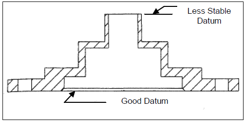
Figure 2. The Most Influential Feature
(S2) A good datum feature should be easily accessible for assembly and manufacturing. See Figure 3 for an example on an Engine Block.
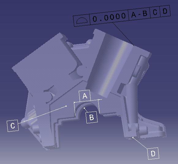
Figure 3. Engine Block with Good Datum Features
(S3) A good datum feature should be easily accessible for inspection and gauging. See Figure 4(a-b) for an example [Bruce Wilson, GD&T Application and Interpretation, 165].
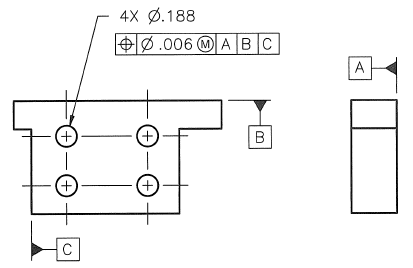
Figure 4(a). A GD&T Drawing with Good Datum Features
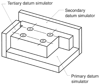
Figure 4(b). Potential Inspection Setting
Datum Reference Frame
A Datum Reference Frame (DRF) is a set of three mutually perpendicular planes, established from datum features; see Figure 1 for a DRF example. A component, either a part or subassembly, is required to have at least one DRF to constrain the component. Figure 5(a-d) [ASME Y14.5-2009, 54] shows the steps in constructing a DRF.
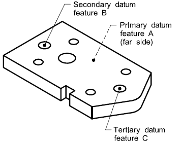
Figure 5(a). Three Datum Features
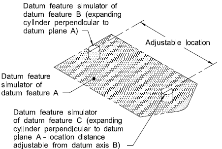
Figure 5(b). Theoretical Inspection Gauge
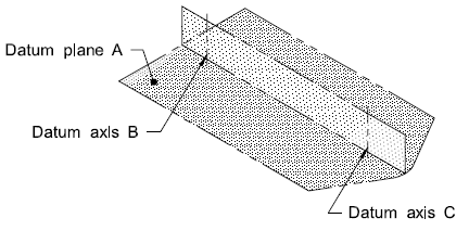
Figure 5(c). Datums derived from Datum Features
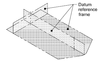
Figure 5(d). Datum Reference Frame
Note: A DRF with three datum planes is generally used to locate a component. It is also common that machined components use DRFs of one or two planes.
DRF Considerations
(C1) Identify the body of a part
The body of a part is the main portion of the part, excluding appendages and extensions. Datum Features should come from the body of a part.
(C2) Identify Functional Requirements
Find the gap and flushness requirements, as well as the mating features, flanges, holes, and slots.
(C3) Identify Process Requirements
Determine the process impacts, such as gravity, tool position, accessibility, checking repeatability, and historical part capabilities.
Get the DE Focus every month by joining DCS's Newsletter
Click here to sign up to receive the DE Newsletter
Editors:
Ying Qing Zhou
Earl Morgan
Victor Monteverde


North American Innovation Center
28064 Center Oaks Ct A, Wixom, MI 48393
Call us: +1 (248) 504 6200


No Comments Yet
Let us know what you think