 This case study is based on work done for a multi-regional aerospace and defense OEM. Due to safety concerns and NDA agreements, the company and product names have been omitted.
Keeping the customer happy is important...for all our safety
Customer Details
The customer is a multi-regional manufacturer producing aircraft at an advanced pace. The output requirements for their facilities are abnormally high for the industry, requiring the production of well over 2000 aircraft a month. The aircraft is a 9 meter long single seat military strike craft.
 The manufacturer is concerned that an unacceptable amount of aircraft are arriving at final storage before being sent to their customer at which point they are failing inspection. The primary reason for inspection failure is a non-conformance in the wing position which could potentially compromise the structural integrity of the aircraft and risk damage or harm to the pilot in inclement weather conditions. The current repair method for the issue are designated rework teams at each plant that are able to reset the wings by partial dis-assembly, stabilization of the structure and re-riveting the wing in place using shimming for additional structural support. With 36 people in each team to accommodate the volume of production, five plants and three days spent each week to repair the issues, the company estimates that it is using 4320 hours of labor per week on rework and non-conformance issues related to the wing assembly. Over the course of six months, using roughly 34,560 hours, this is estimated to cost 3.1 million dollars.
The MKII Version Currently in Production
The manufacturer has a highly skilled dimensional team with experience in 3D analysis and variation analysis working to resolve the issue, but is looking for additional personnel to help investigate solutions to the issue. DCS was called to supplement the team and assist in finding a resolution.
 The aircraft being built has a very large production volume. With such large volume, all rework and non-conformance issues become exceedingly expensive. With budgets constantly being reduced, and the customers demanding faster and faster delivery times, it is key to optimize both assembly processes as well as to reduce Tooling as much as possible.
The current issue being addressed is a non-conformance from variation in the wing box during final assembly. The final position of the wings when assembly is complete needs to be parallel. The acceptable tolerance ranges for wing placement is +/-8 mm. Anything more causes additional drag, as well as potentially dangerous force on the wing structure from wind turbulence. Compromising the structural integrity of the aircraft is not acceptable, and so high accuracy tooling is used to assemble the wing structure to the primary fuselage. This has controlled the variation to within acceptable levels for a majority of cases. However, there is still a percentage of cases, approximately 4% to 7%, that have a non-conformance and require expensive and time consuming rework to adjust the wing position to within acceptable limits.
The studies completed in 3DCS Variation Analyst have determined the primary contributor to the issue, with a total contribution of 40%, stemming from the Tooling itself.
 The Dimensional Team at the manufacturer site investigated the Tooling and determined that there were two sets of Tooling from different manufacturers. The legacy set pulled from a previous version of the aircraft had much larger variation, with differing amounts on each Tool. Due to cost constraints, the legacy Tooling had been modified to work with current production to accommodate the high volume of assembly. However, because it had original been for a smaller wing version of the aircraft, the modifications still left it with a larger amount of variation than the new Tooling manufactured specifically for the latest version of the aircraft.
The MKI Version, Now Out of Production
The Wing to Wing Box assembly is often a cause of trouble at final assembly in aircraft. The wings are required to be parallel, and the attachment often requires shimming, expensive Tooling and a skilled assembly team. Even with these provisions, the process is often time consuming, expensive and adds weight to the aircraft.
The manufacturer investigated the cost of fabricating new Tooling to replace the legacy Tooling, but the cost was too high for approval, and would take too long to manufacture and ship. Management required a solution sooner, and did not want to continue production using the existing legacy Tooling.
 A Determinant Assembly solution was proposed by the Dimensional Team at the manufacturer, but without validation or prototyping, the solution was rejected. DCS proposed two parallel studies be conducted, one as a validation of simulation results compared to as-built results in order to prove the accuracy and reliability of the simulation results, and the second a test of the determinant assembly solution proposed by the manufacturer’s Dimensional Team. In order for the manufacturer’s management team to trust the results, it was decided that the Dimensional Team would conduct the validation study while the DCS team conducted the Determinant Assembly study. This would allow both studies to be completed around the same time, and should they prove successful, would allow faster implementation of the results.
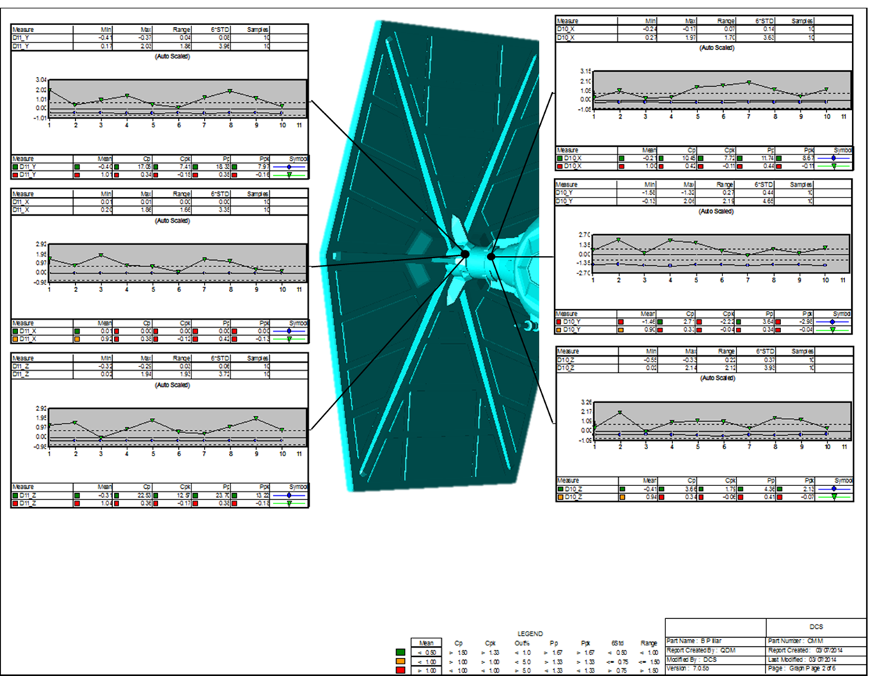
The Validation Study used the legacy aircraft in order to take advantage of the historical measurement data taken at time of production. With thousands of measurement data files in the system from dimensional inspection of the aircraft during its nine year production, including excel files from hand measurements, CMM outputs from the wing suppliers and visual scanning outputs from the final assembly site, there was enough data to conduct a thorough study.
Utilizing the QDM WEB system the manufacturer created a series of new report templates and imported the data files. Outputting the reports, they were able to determine key areas that could be modeled in 3DCS. This was important, as modeling the entire aircraft in 3DCS, which had not been done for this legacy aircraft at the time, would be too time consuming for the study.
Choosing the key areas to model, in this case the attachment points between the wing and the fuselage on one wing, and the Tooling used to assembly the aircraft, the analysis was run on several machines over the weekend to produce a large enough sample size for higher accuracy of results, in this case 10,000 simulated builds.
The results were loaded into the QDM WEB system, and the same reports were generated using the simulation results. These were then used to create Comparator Charts to test the results against one another and determine the correlation. With the results being deemed 85% accurate as compared to the as-built data, the reports were converted into a presentation to be delivered to management for approval.
 At the same time, the DCS team modeled the Determinant Assembly process based on the 2D drawings delivered by the manufacturer to the modeling team. Because the documents were associated with a military aircraft, additional precautions were taken, and the DCS team was moved to the manufacturer’s site in order to contain the information on location.
The designs called for a design change in the attachment location, allowing the wing to be inserted into the fuselage arm and self-support its weight during riveting. Additional support material was required to build up the attachment area, but could be quickly built using the 3D printing available on the manufacturer’s site, and could be constructed from light weight composite material. This would replace a majority of the shimming, and would overall reduce the weight of the aircraft. The simulation was conducted using 10,000 simulted builds as well, and showed a very low percentage of non-conformance. With critical to quality areas designated, and a measurement plan exported from QDM WEB, the results were converted into a presentation including an inspection validation process for production to confirm success.
 Due to the design changes and adjustments required to implement the changes, the manufacturer’s management team was cautious about moving forward. They designated a test plant that produced a lower volume of aircraft to test the solution under the supervision of the Dimensional Team.
The kit for the wing was 3D printed on site using the 3D printer bank, which consisted of thirty machines linked together, and was connected to the first set of aircraft. These were then assembled without the Tooling using only basic fixtures and cranes to set the wing in place. After the first sets of aircraft were assembled, they were inspected using the visual scanners at the plant, and then inspected by the quality team in detail before being approved for test flight.

Unfortunately, there was an incident involving a dissident group of rebels that delayed the test flight. Production was paused while security was re-established. The first line of aircraft assembled with the new process were needed to assist in the security measures, and performed well in all flights. The project was approved for widespread use pending the conclusion of these events.
The project was deemed a success. After six months, the company estimated reducing rework on the wings per week down to 4 hours from 24, a time savings of 3600 man hours per week that would have been spent on rework and resetting of wings. With six assembly lines at each plant, and five total plants, a total of 62 Tools were retired, saving the company maintenance and the cost of the Tools on the next project (estimated to cost approximately 1.2 million dollars per Tool, saving the project 74.4 million dollars in addition to maintenance and delivery costs). The overall cost reduction was estimated at 90 million dollars, in addition to the time savings.
Necessary Disclaimer: We hope you enjoyed our article. All images, names and things related to Star Wars do not belong to us, and we do not represent in any way Lucas Arts or Disney. We apologize if anyone’s feelings were hurt in the creation of this article. Please go to the theaters to see the new movie, Star Wars: The Force Awakens and enjoy your holidays!
Images courtesy Wookiepedia, http://starwars.wikia.com/wiki/Main_Page
http://www.comicbookmovie.com/fansites/markcassidycbm/news/?a=122516
http://www.iconarchive.com/show/star-wars-vehicles-icons-by-jonathan-rey/Tie-Fighter-01-icon.html
CAD model courtesy of GrabCAD https://grabcad.com/library/sw-tie-fighter-1


North American Innovation Center
28064 Center Oaks Ct A, Wixom, MI 48393
Call us: +1 (248) 504 6200


No Comments Yet
Let us know what you think