This short video simulates a front rail, essentially two pieces of sheet metal being welded together. The model is designed to measure estimated springback. This simulation uses 3DCS Variation Analyst 7.3.2.0 in CATIA V5 R24, and includes the 3DCS FEA Compliant Modeler Add-on. This simulation was completed by DCS"s senior variation analyst, Gary Bell.

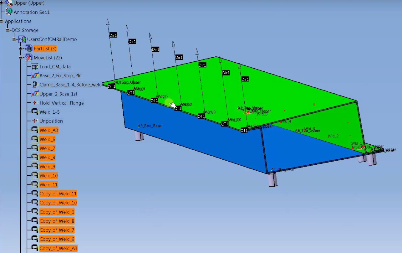
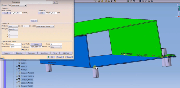
This is a demo to show you how weld sequence can affect your final results. In this model we’re measuring the springback between the base part and the tool. You can see above that we’re welding across the top flange from the left to the right. Then you can see we have additional welds if you want it from the right to the left. So with the original welds intact, if I do a nominal build and go into that measurement you can see the springback measurement, which is between the tool and the part, is approximately 3.12 mm.
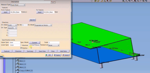
Now if I toggle these welds, now I’m welding this way across, from right to left. I do a quick nominal build (which might take a moment depending on the number of compliant moves). You can see the gap is 2.57 mm, down from 3.12 mm. So starting to weld from here over locks this area first and the springback actually decreased.
The primary difference is whether the weld moves are considered all one move (happening simultaneously) or individual moves (happening in sequence). As this case has the welds modeled as individual moves, the software recalculates the stiffness and combines it at the welded point. This occurs after each move, thereby deforming the part piece by piece and causing different results depending on the particular sequence.
In this example, we get different deformation results as one scenario pulls the measured side first, and then begins to weld away from it. This locks in that side, causing more variation in the other direction. When you begin on the far side and weld towards the measured point, the variation stacks up towards the measurement, causing greater deformation at the measured point.
This is just one example. If modeled to weld from the center, you would get different results as well.
Check out the video on youtube (Creative Commons License) and see for yourself.
Interested in more? Download the whitepaper "Three Methods of Modeling Compliant Parts" and see how FEA Compliant Modeler can increase your model's accuracy by 14%!


2805 Bellingham
Troy, Michigan, USA 48083
Call us: +1-248-269-9777


No Comments Yet
Let us know what you think